![]()
![]()
![]()
![]()

![]()
![]()
![]()
![]()
![]()
![]()
|
|
|
|
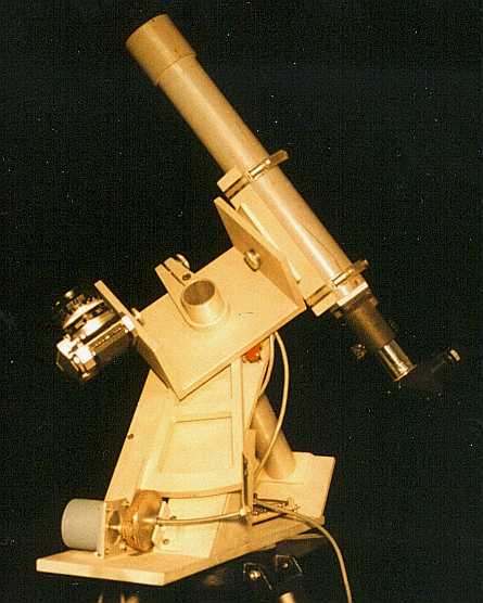
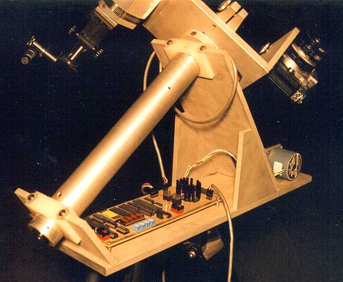
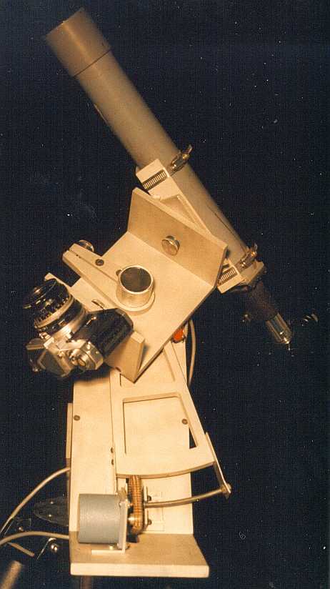
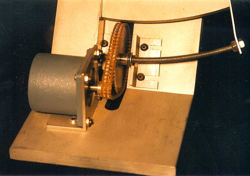
Prior to obtaining my Meade LX200, I wanted to do some astrophotography with my SLR 35mm camera. In order to take advantage of dark skies outside of the city where I lived, I designed a portable equatorial mount. It is based on a couple of articles in Sky & Telescope, dealing with a portable camera mount, a low cost tangent arm and how to make a polar alignment reticule. The overall mount is machined from .375" aluminum plate and is preset to my latitude (36.02°). The polar axis is 2" diameter aluminum tubing that has been turned down slightly on each end. The ends then mate into "bearing blocks" of virgin nylon. The polar axis also contains an objective and eyepiece with the polar alignment reticule. Right ascension tracking is accomplished with a tangent arm driven by a stepper motor. The end of the tangent arm holds a 15° section of 1/4-20 rod. This rod is curved to the same radius the rod is from the center of the polar axis. A 55 tooth gear was tapped to drive the 1/4-20 rod. The gear is held in place by a piece of 90° aluminum on each side of the gear. Thrust washers between the gear and the holding brackets reduce the lateral friction of the gear. A belt drive connects the 55 tooth gear to a 12 tooth gear on the stepper motor. The belt helps to reduce vibration created by the stepper. The camera platform is a U shaped attachment to the polar axis, that can be turned independently for aiming. On one side of the U is a captured 1/4-20 bolt for holding the camera. On the other side of the U is a guiding telescope with a 588 mm focal length objective. This telescope can also be moved in declination in order to find a suitable guide star near the object being photographed. The controller for the mount is based on an RCA 1805 microprocessor. On startup, the CPU reads the value of 4 hex rotary switches to obtain an initial right ascension rate value to load into a down counter. Every time the counter counts down to zero, a pulse is produced which will move the stepper by one step. My default rate has the stepper running at 31 steps/second. A four digit hex display shows the current value in the down counter. A two button hand paddle allows for adjustment in tracking. Pressing the right button alone will increase the RA rate by a fixed value. Pressing the left button alone will decrease the RA rate by a fixed value. Releasing the right button alone, or the left button alone will return the RA back to the current value. As previously mentioned, the initial RA current value is taken from the hex switches. This value can be modified from the hand paddle. In order to increase the RA rate you press the right button and then while holding it down, press the left button. The hex display will start increasing in value about one unit per second. Releasing both buttons will leave the default RA rate at the new value. To slow down the default RA rate, first press and hold the left button, then press the right button. The hex display will start decreasing in value about one unit per second. Releasing both buttons will leave the default RA rate at the new value. The unit is designed to run off 12 VDC and draws about 1 Amp. Limit switches protect the tangent arm from traveling too far. There are no declination slow motion adjustments.
|
|
Please address general comments to web@dv-fansler.com This page was last modified:
01/22/14 |