|
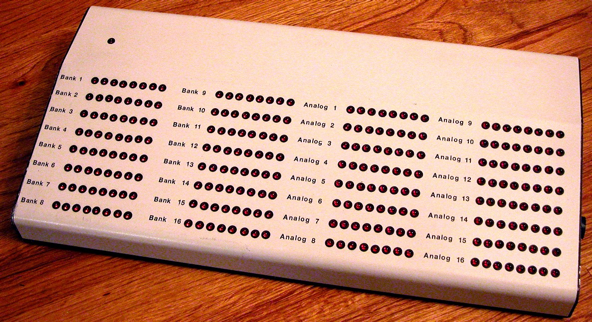
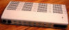
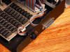
 The finished controller in what was originally designed to be a keyboard case.
The LED in the upper left corner is a power indicator. Each of the other
LEDs is an indicator for each of the 256 individual outputs. The left two
groups total up to 128 individual off/on outputs. The right two groups are
combined to form 16 analog outputs (0-10vdc). Each output has 256 steps.
The finished controller in what was originally designed to be a keyboard case.
The LED in the upper left corner is a power indicator. Each of the other
LEDs is an indicator for each of the 256 individual outputs. The left two
groups total up to 128 individual off/on outputs. The right two groups are
combined to form 16 analog outputs (0-10vdc). Each output has 256 steps.
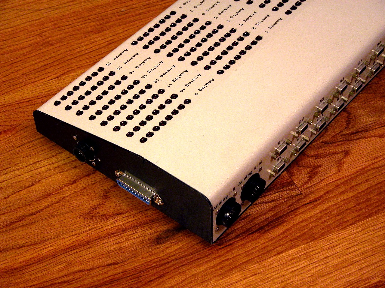
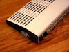
 The
back of the unit shows the 16 DB9 connectors (each has 8 outputs plus ground).
The two large circular connectors on the left are the analog outputs. Each
16 pin connector has an analog signal and a ground signal for 8 analog ports. The
back of the unit shows the 16 DB9 connectors (each has 8 outputs plus ground).
The two large circular connectors on the left are the analog outputs. Each
16 pin connector has an analog signal and a ground signal for 8 analog ports.
 This end/back view shows the analog connectors again on the back.
Visible on the side is the 36 pin Centronics connector, which accepts a standard
printer cable, linking the controller to a PC. This end/back view shows the analog connectors again on the back.
Visible on the side is the 36 pin Centronics connector, which accepts a standard
printer cable, linking the controller to a PC.
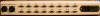 A full back view of (starting from the left) the two 16 pin analog
connectors, 16 DB9 connectors and a power input connector for 115vac. A full back view of (starting from the left) the two 16 pin analog
connectors, 16 DB9 connectors and a power input connector for 115vac.
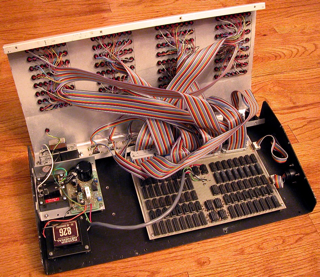
Looking inside the controller is the power supply on the left, the main board
on the right with a maze of ribbon cable going to the LED indicators.
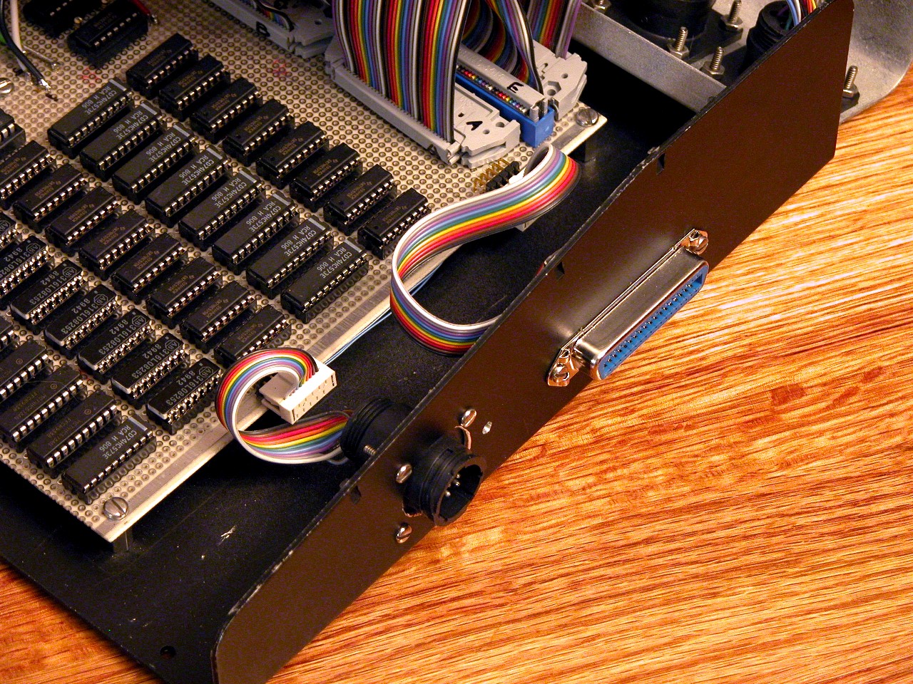
An inside view of the connection between the main board and the Centronics
connector. The additional 9 pin connector allows for expansion.
 Main board mounted in the case. The power supply shown was an old
switcher that developed too much noise to be of use. Main board mounted in the case. The power supply shown was an old
switcher that developed too much noise to be of use.
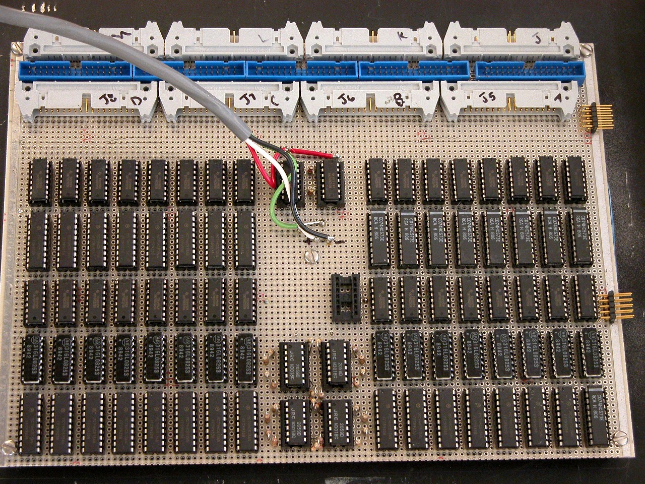
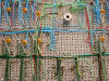
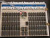 This is the top of the main circuit board. The top two rows of ICs are
for channels 1-128. The bottom three rows are for channels 129-256 and
include the R2R resistor ladder for digital to analog conversion. The four
ICs in the center bottom are op amps to raise the output of the R2R ladders from
0-5vdc to 0-10vdc. This is the top of the main circuit board. The top two rows of ICs are
for channels 1-128. The bottom three rows are for channels 129-256 and
include the R2R resistor ladder for digital to analog conversion. The four
ICs in the center bottom are op amps to raise the output of the R2R ladders from
0-5vdc to 0-10vdc.
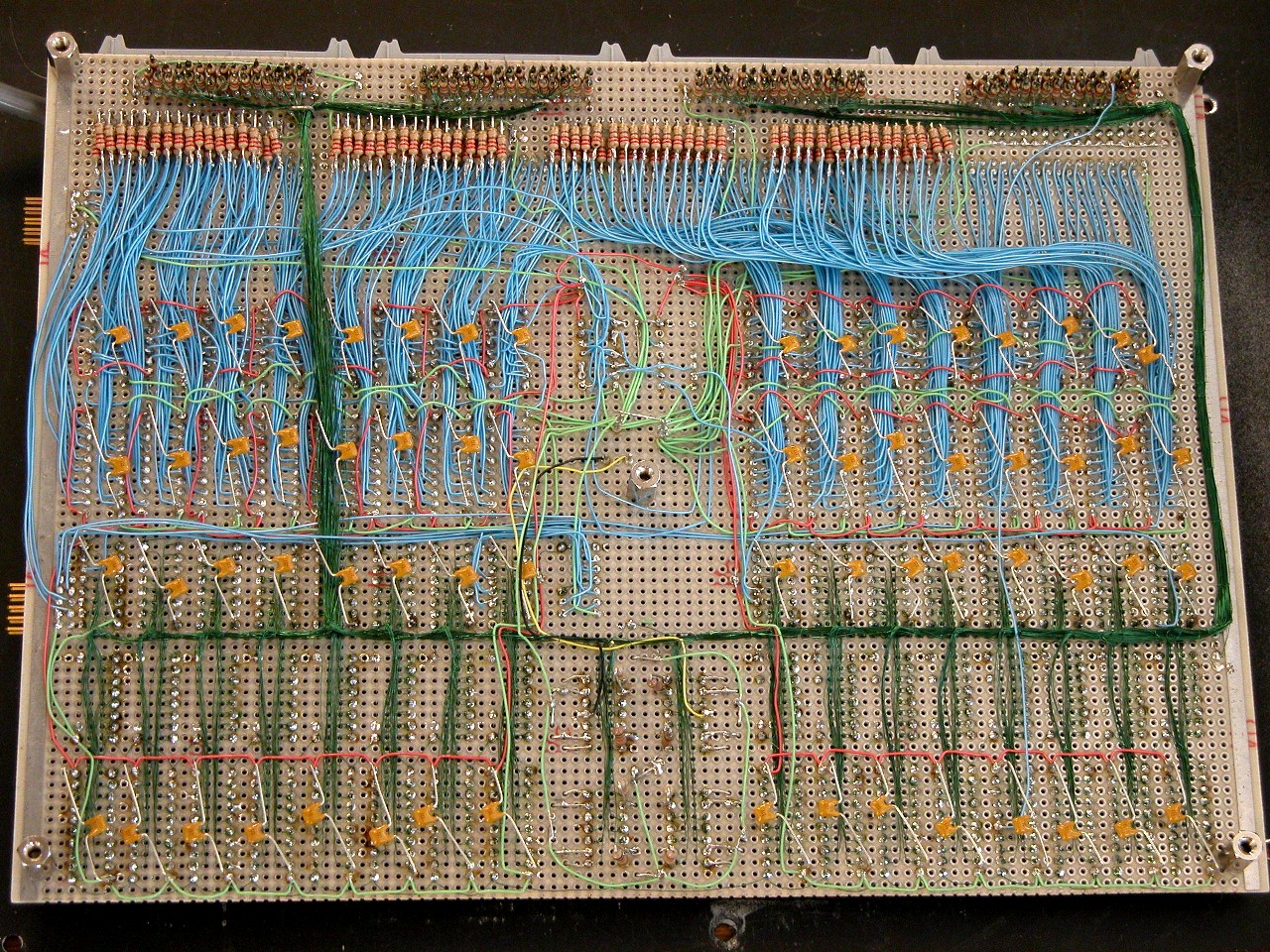
This is the bottom of the main board. There are two types of wiring on
the board - using traditional wire wrap wire and using the Vector Wiring Pencil.
A closer look at the two types of wire.

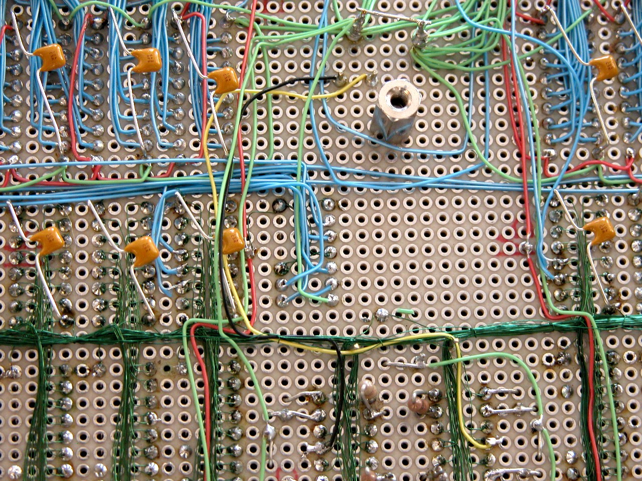
Close up of the wire wrap section. Each IC has a de-coupling capacitor
between ground and +5v.
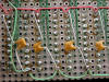
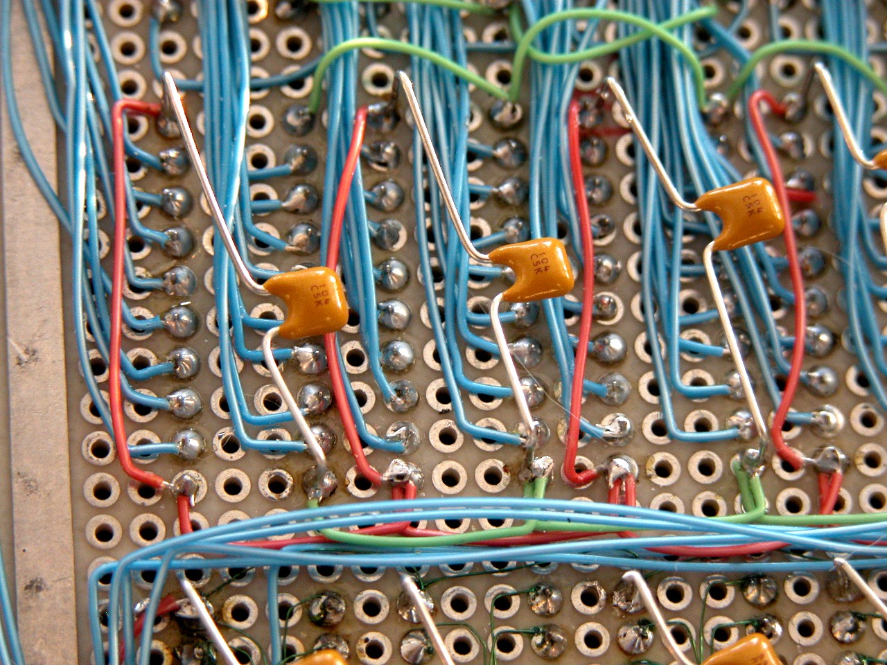
Close up of the Vector Wiring Pencil wiring. This was available during
the mid-late 1970's. It uses a #36 wire that has an insulation that
evaporates at 700°F. So you wire wrap
point to point and then solder the wrapped points. Wire is capable of
carrying 1 amp. A really fast way to build a circuit!
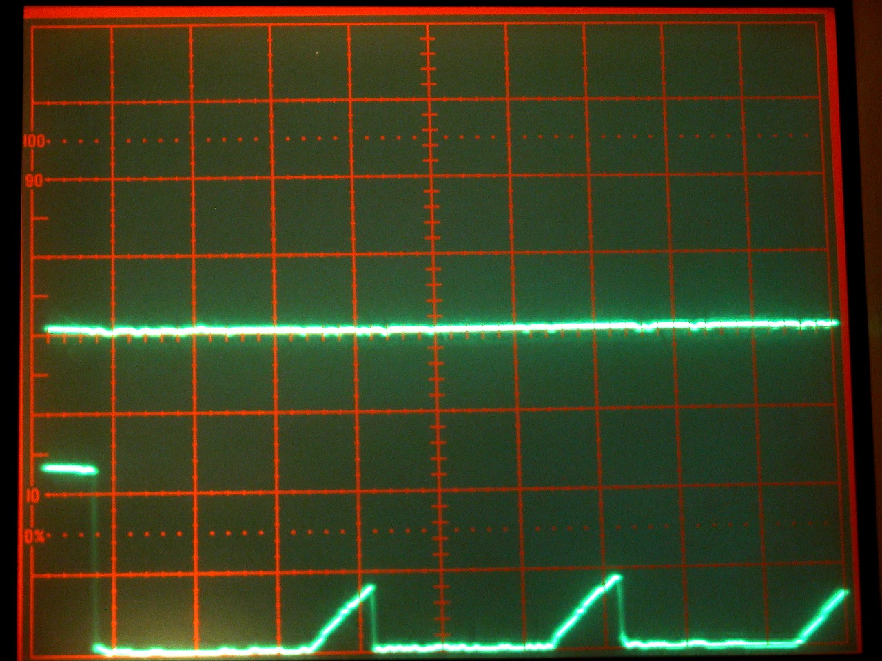
 Picture of the output of *Strobe (pin 1) of the parallel printer port on my
IBM ThinkPad. Vertical is 2v/division, horizontal is 2μsec/division.
Note the signal is only ~1.6vdc Picture of the output of *Strobe (pin 1) of the parallel printer port on my
IBM ThinkPad. Vertical is 2v/division, horizontal is 2μsec/division.
Note the signal is only ~1.6vdc
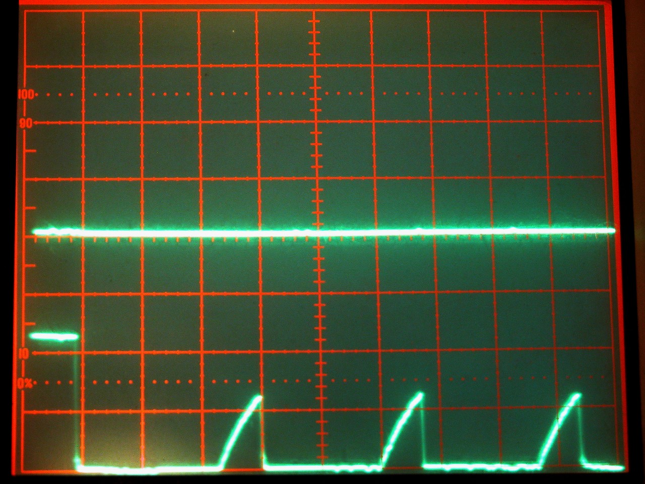
 Same pin, same vertical and horizontal settings, but with a 4.7k pull up
resistor. Signal now has an amplitude of ~2.4vdc Same pin, same vertical and horizontal settings, but with a 4.7k pull up
resistor. Signal now has an amplitude of ~2.4vdc
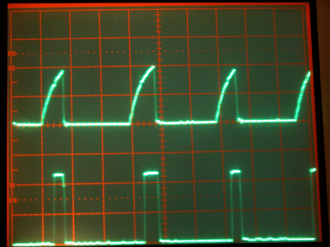
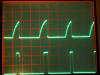 Same
pin, same vertical and horizontal settings. The upper trace is with a 1.8k
pull up resistor, giving a ~4vdc amplitude. The lower trace is the same
signal after having passed through a pair of Schmitt triggers to clean the wave
up. Same
pin, same vertical and horizontal settings. The upper trace is with a 1.8k
pull up resistor, giving a ~4vdc amplitude. The lower trace is the same
signal after having passed through a pair of Schmitt triggers to clean the wave
up.
|