![]()
![]()
![]()
![]()

|
|
|
|
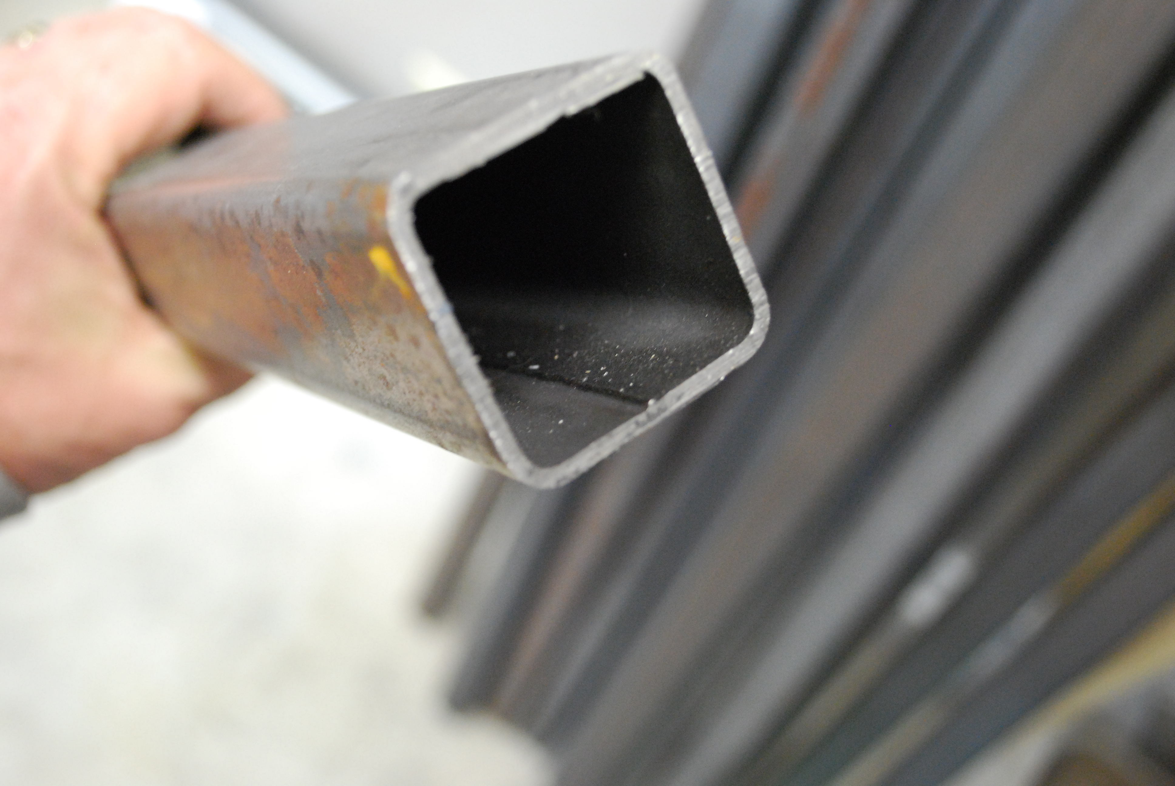
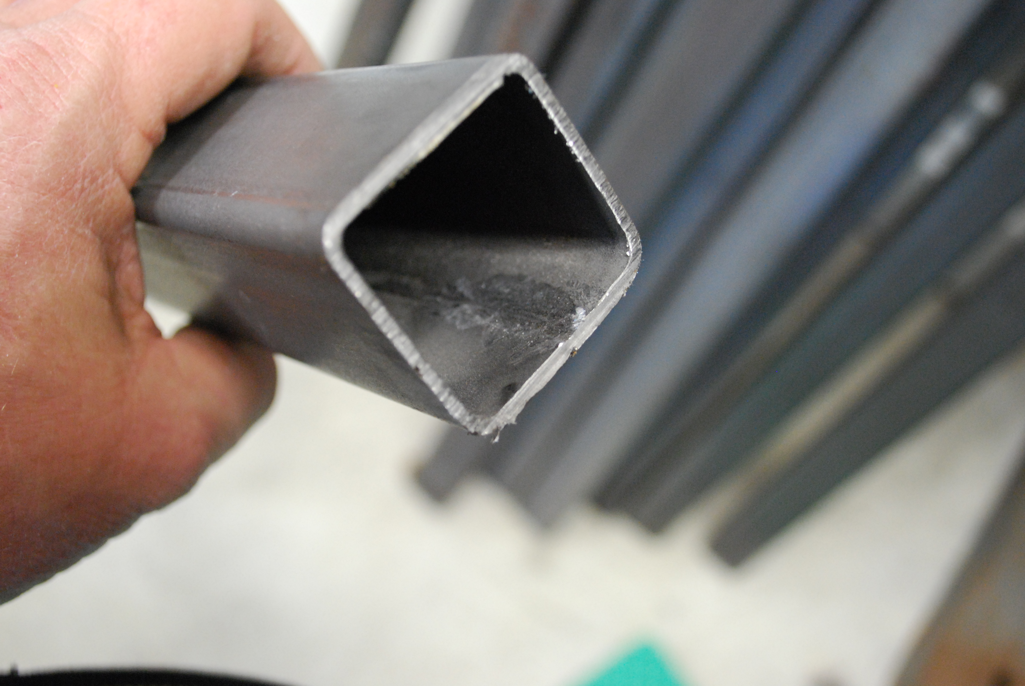
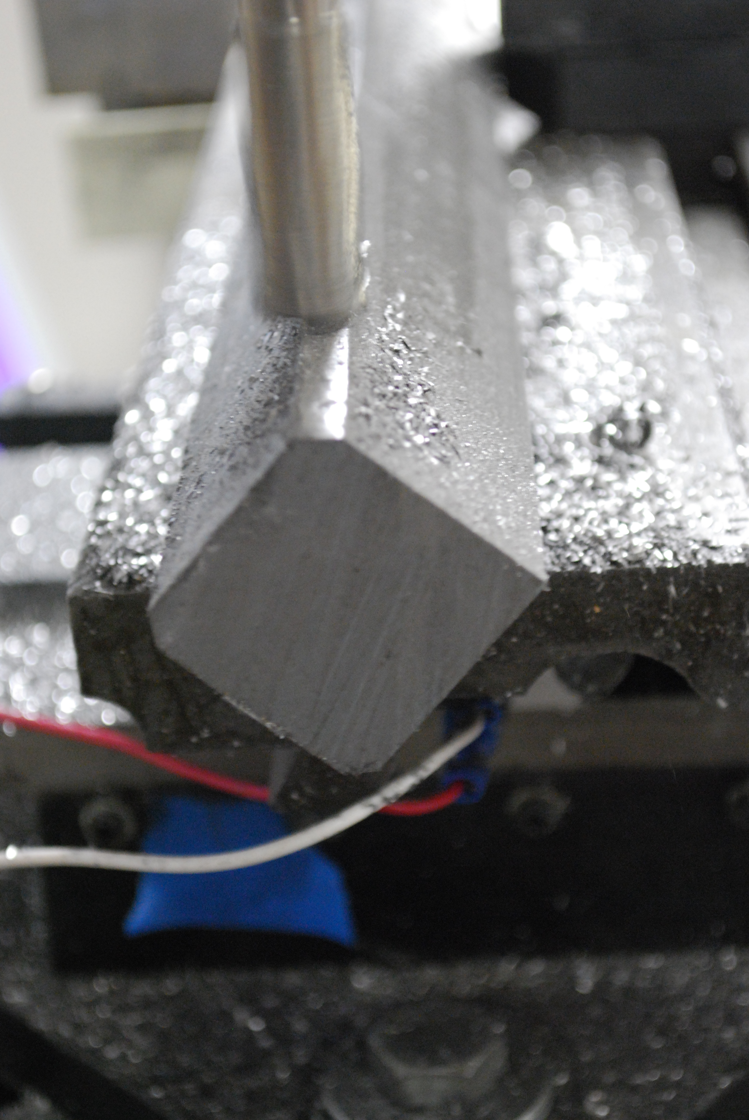
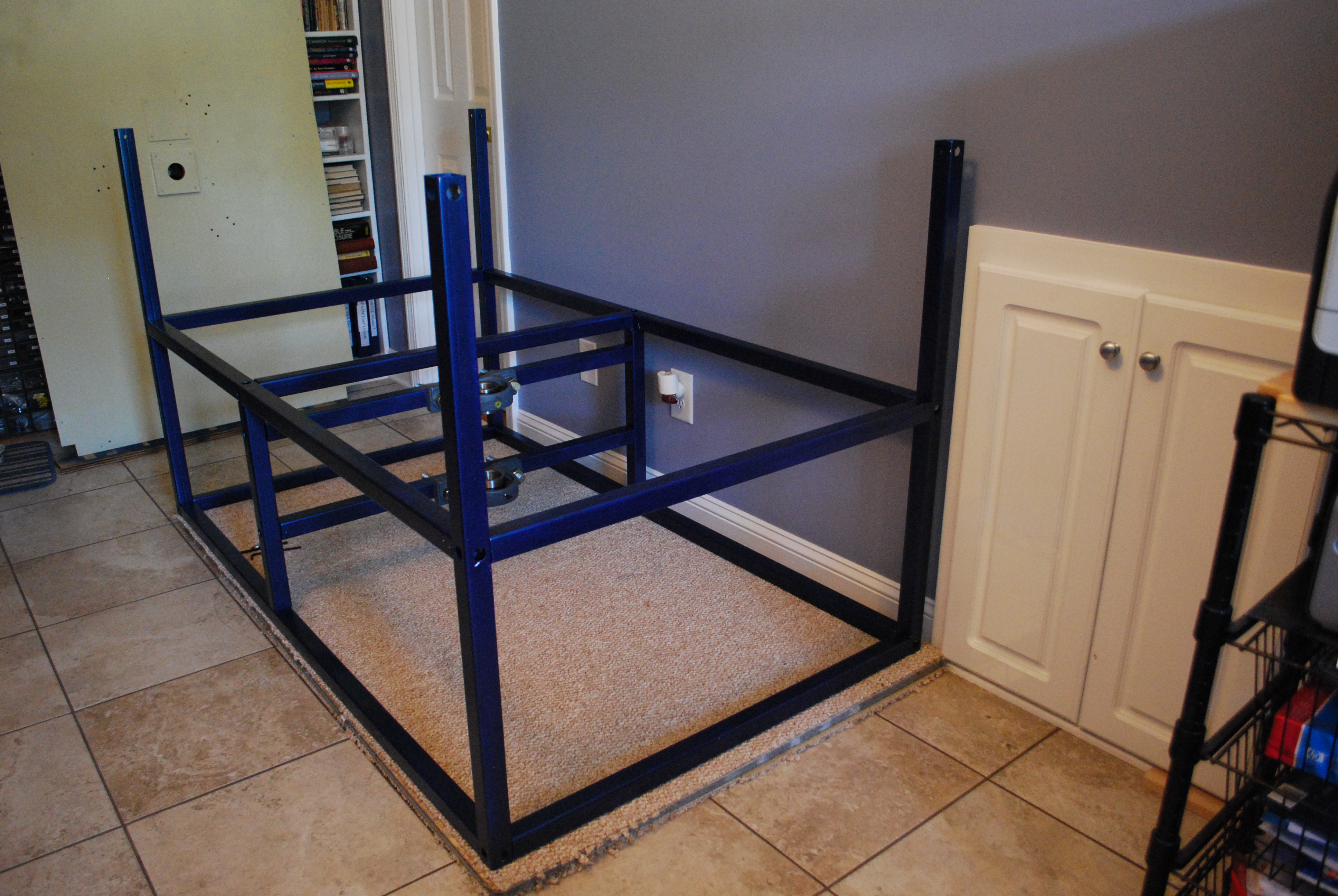
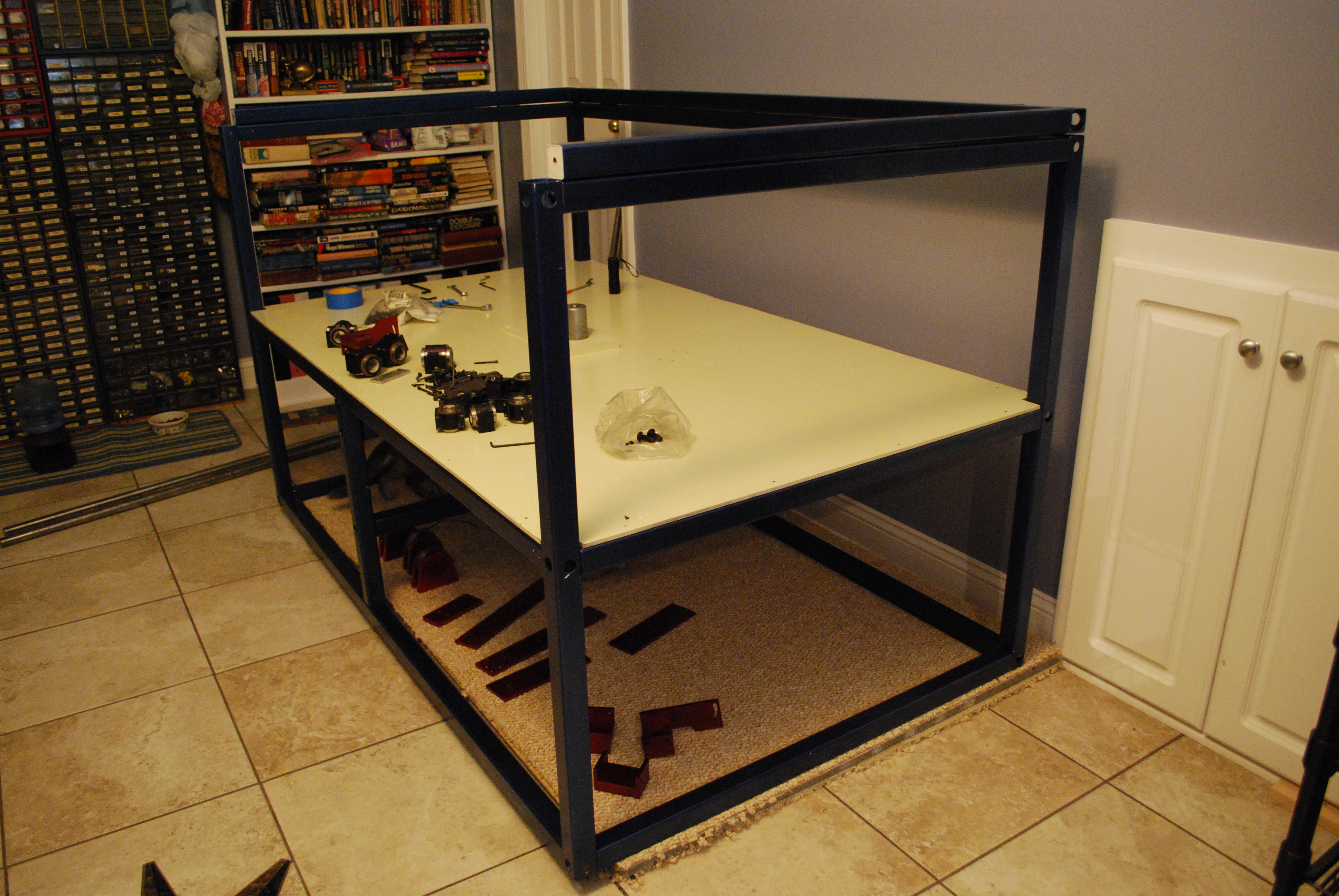
Basic Overview: The frame of the MGM is made of 1.5" square steel tubing. I milled a
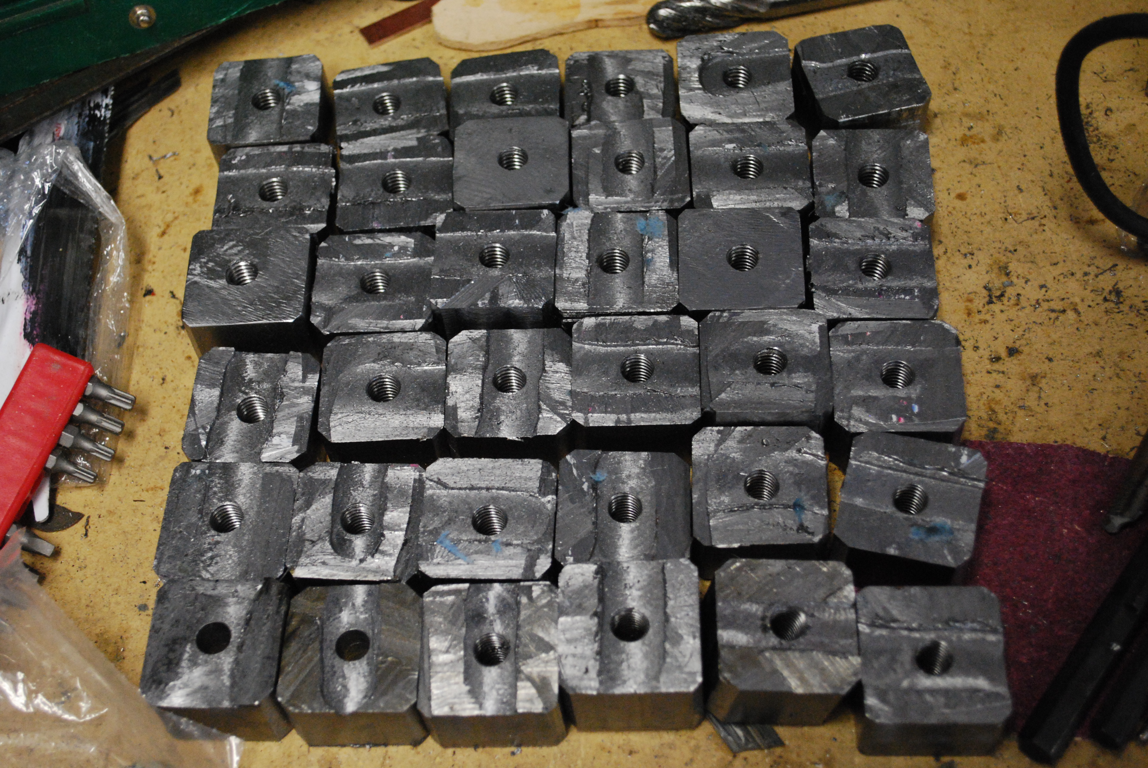
plug from steel which I welded into the end of several tubes. An internal
ridge in the tube was ground down with a Dremel tool. The plugs were
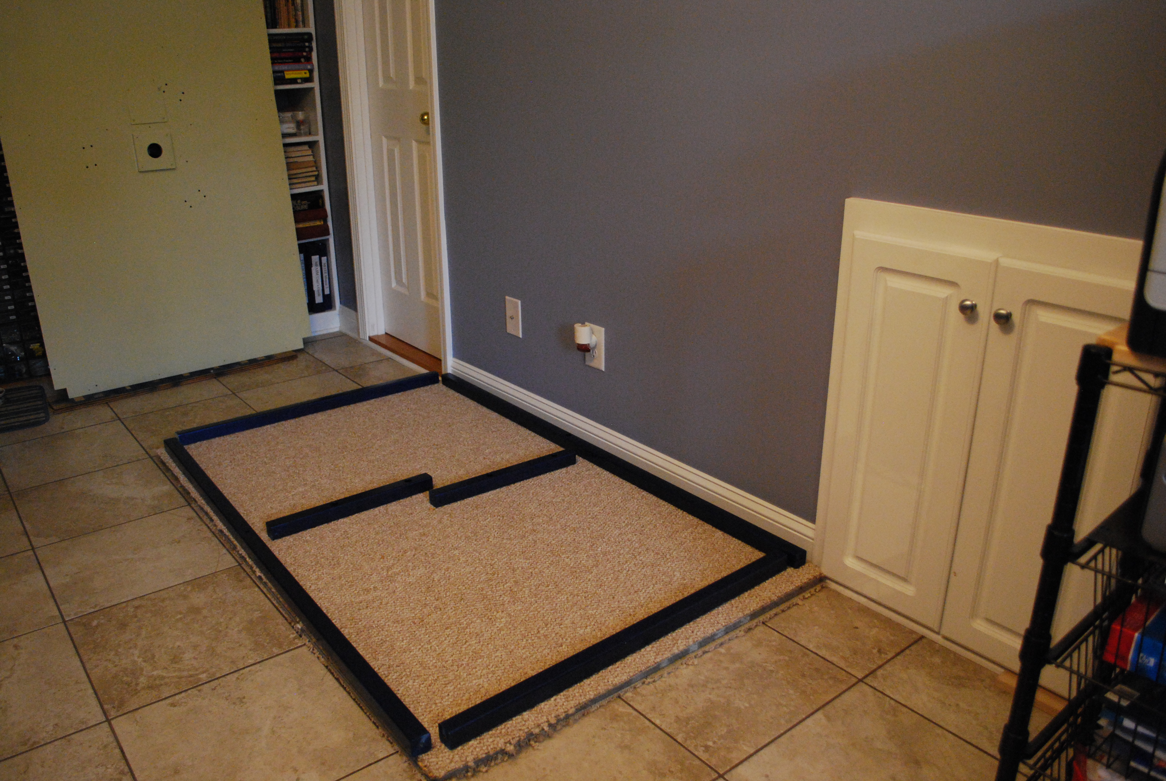
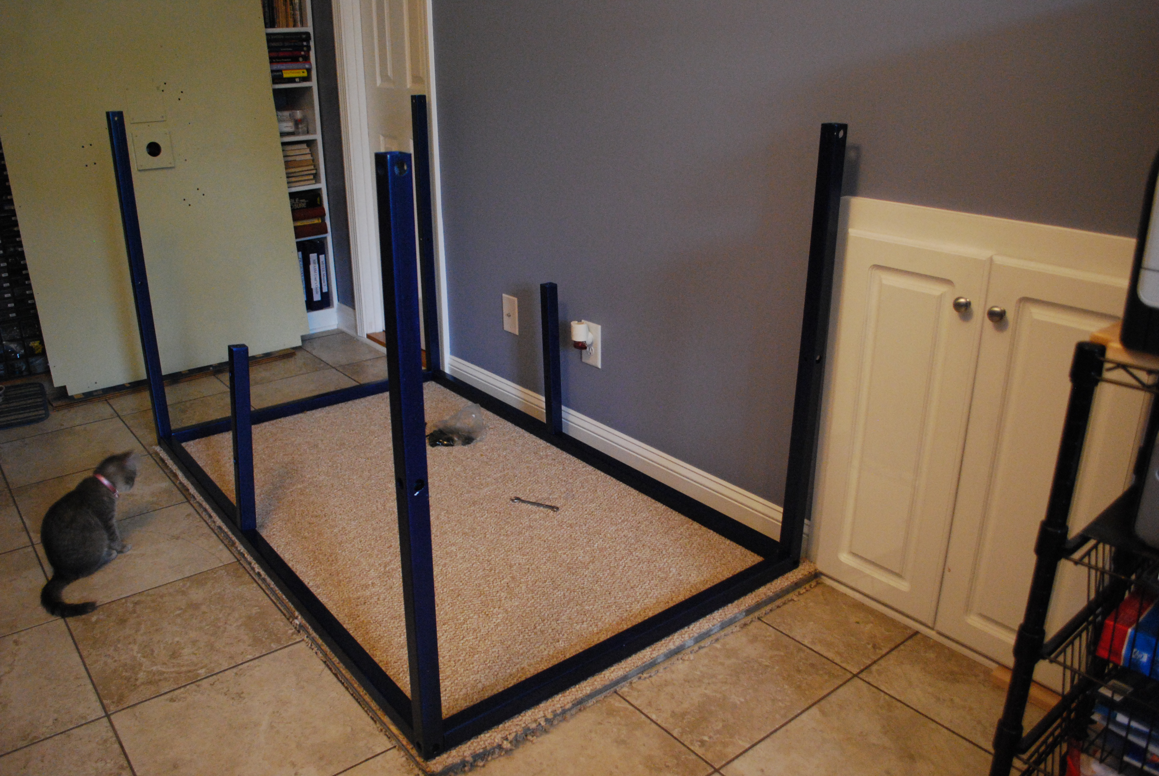
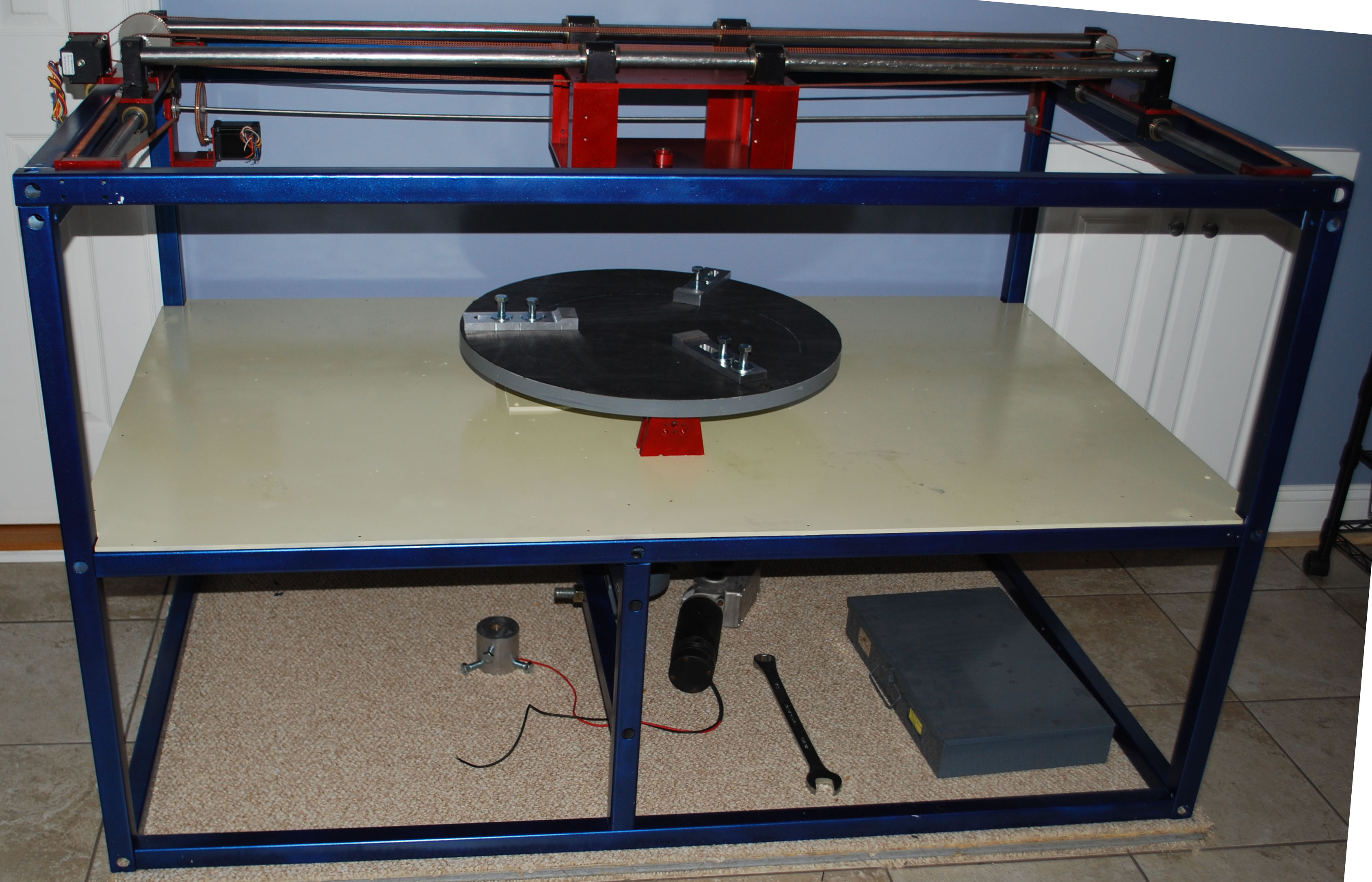
tapped with a 3/8 x 16 hole. Once all the parts had been machine, the frame was painted with a cobalt blue metal flake paint. All moving parts were painted with a red metal flake paint. They really look good. I once did contract electronics for a machine shop - the owner had a tongue-in-cheek saying - "It doesn't matter if it works, as long as it looks good!" Assembly of the MGM finally begin in early September 2009. The frame
sits on a piece of carpet, which had a 3/4" OSB panel on top, and then another
layer of carpet. The series of images below show the frame being
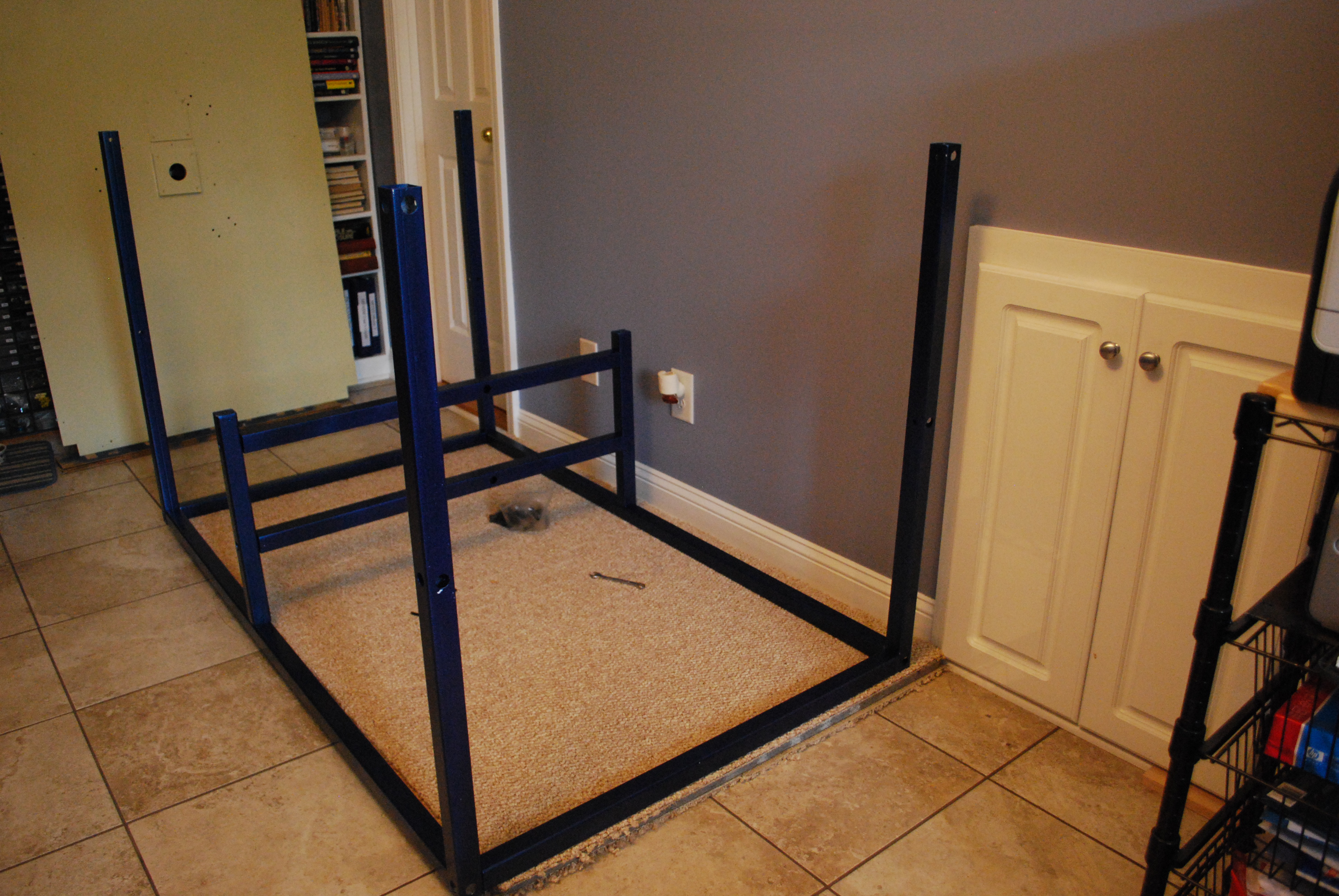
assembled. The frame is screwed together using 3/8 x 16 button head socket
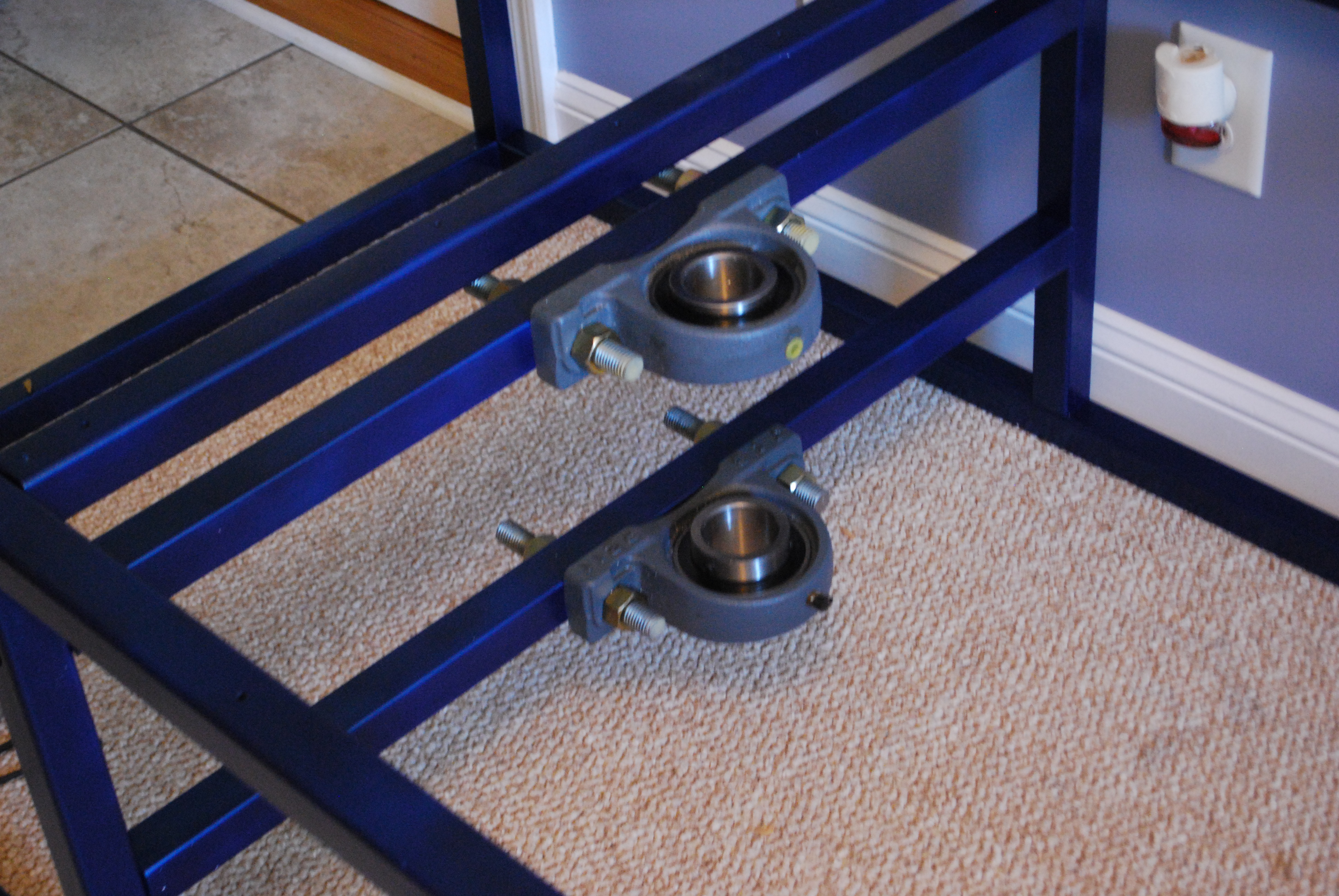
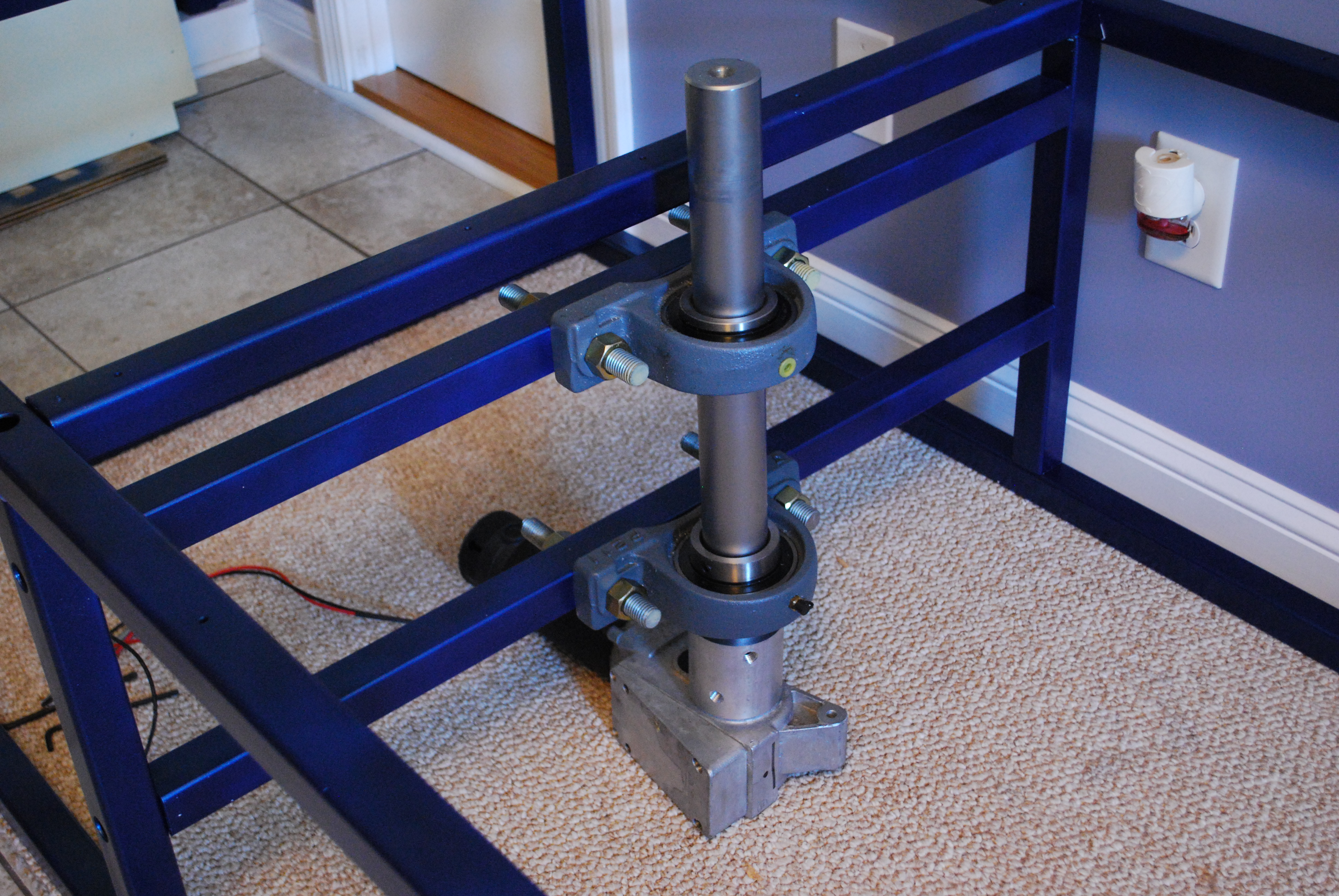
screws. The 24" diameter turntable rides on 3 large bearings, but is attached to a 2" diameter shaft which is attached to the wheel chair DC motor to turn the turntable.
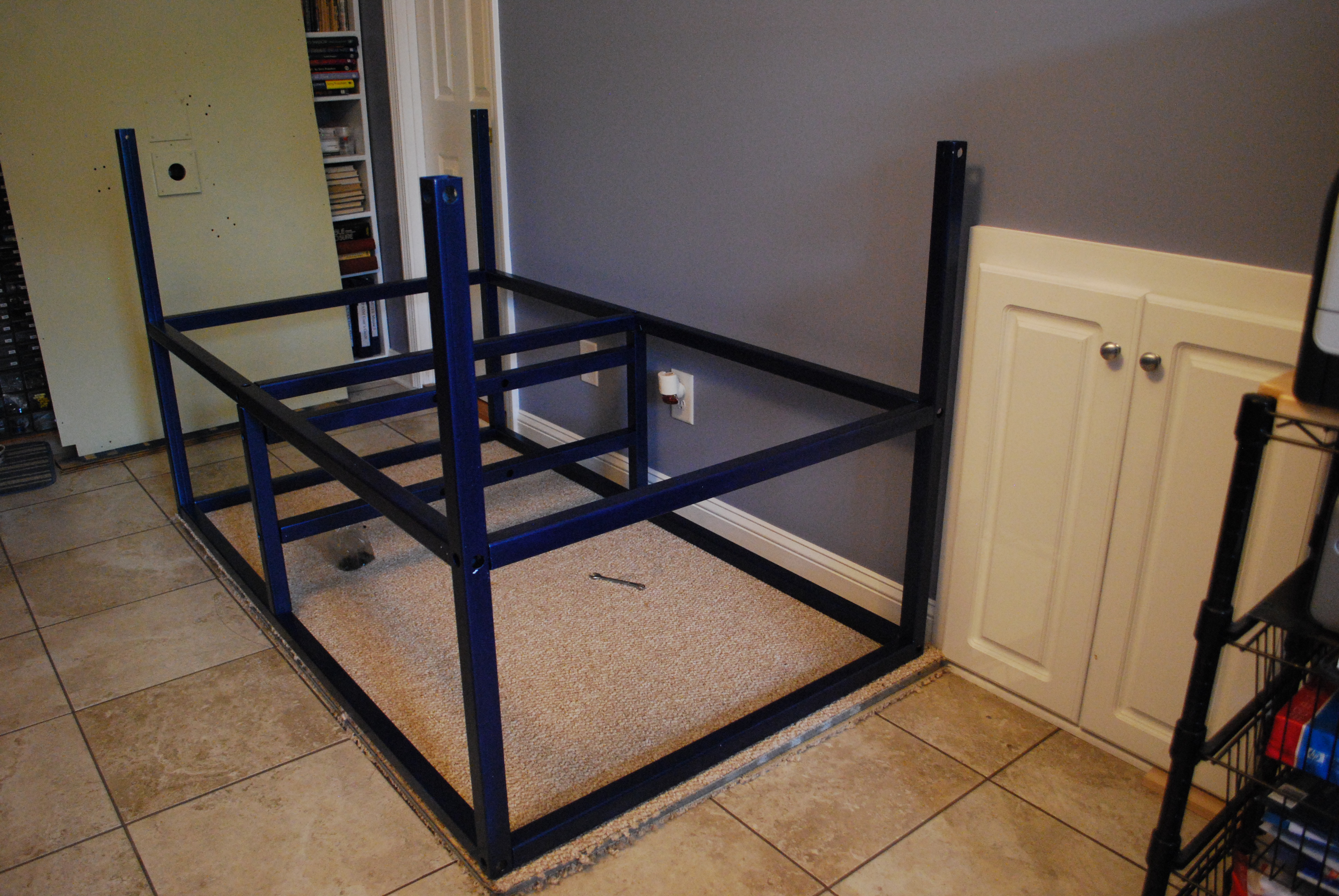
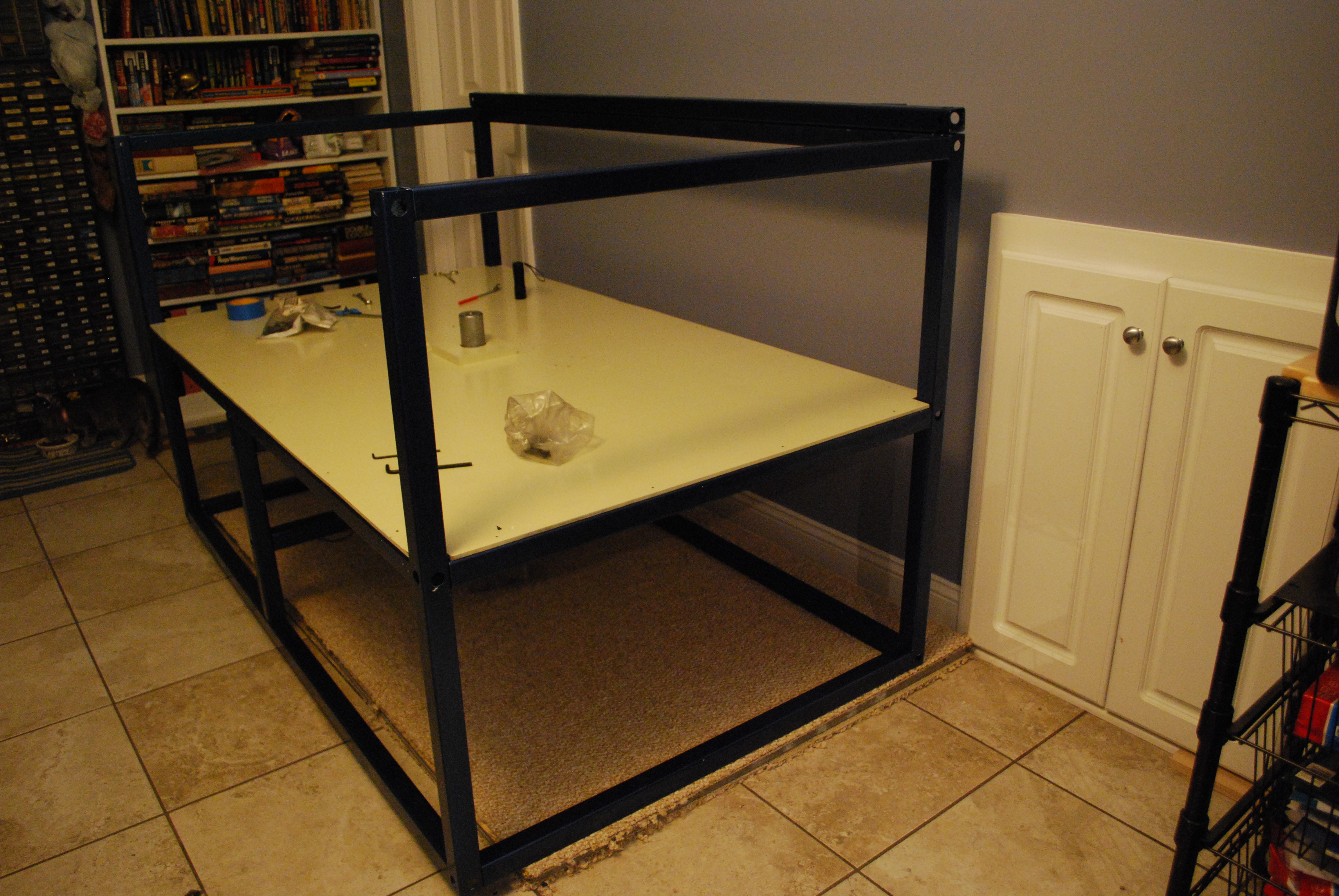
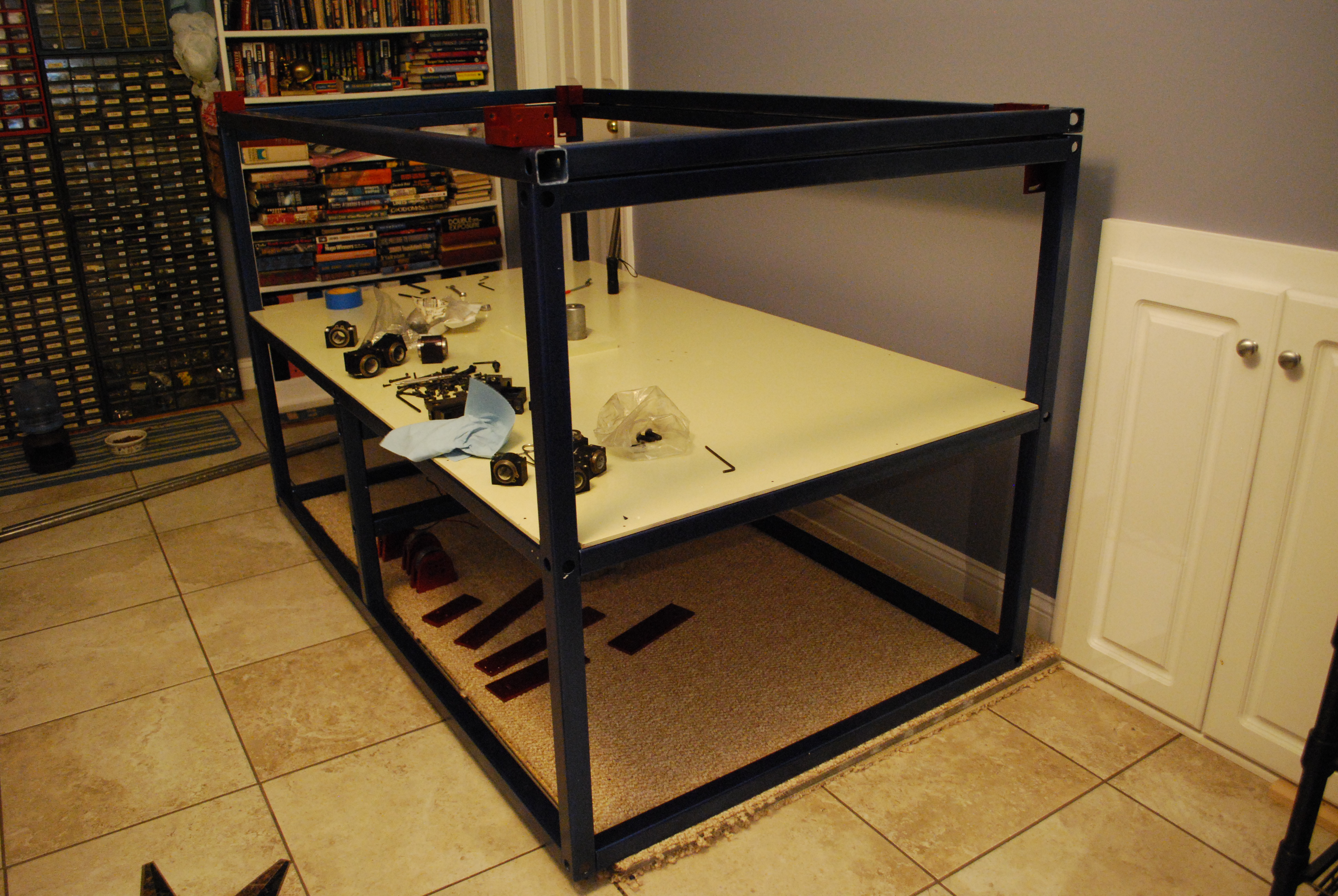
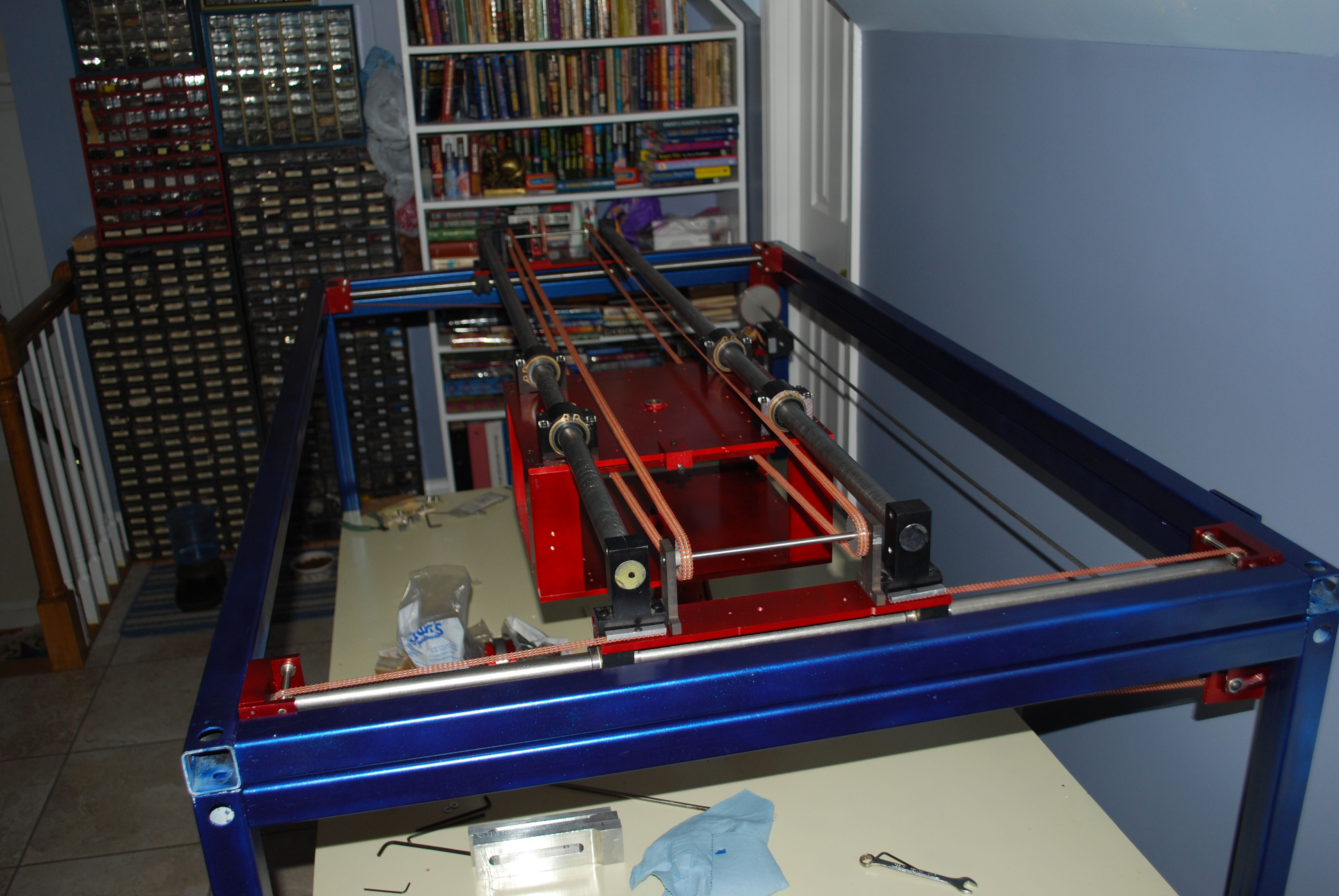
Once the main part of the frame was assembled, the base plate (.25" Aluminum) was screwed in place. Next the top frame work was bolted in place, and the top (which carries the motors and X-Y carriage and is hinged) was put in place.
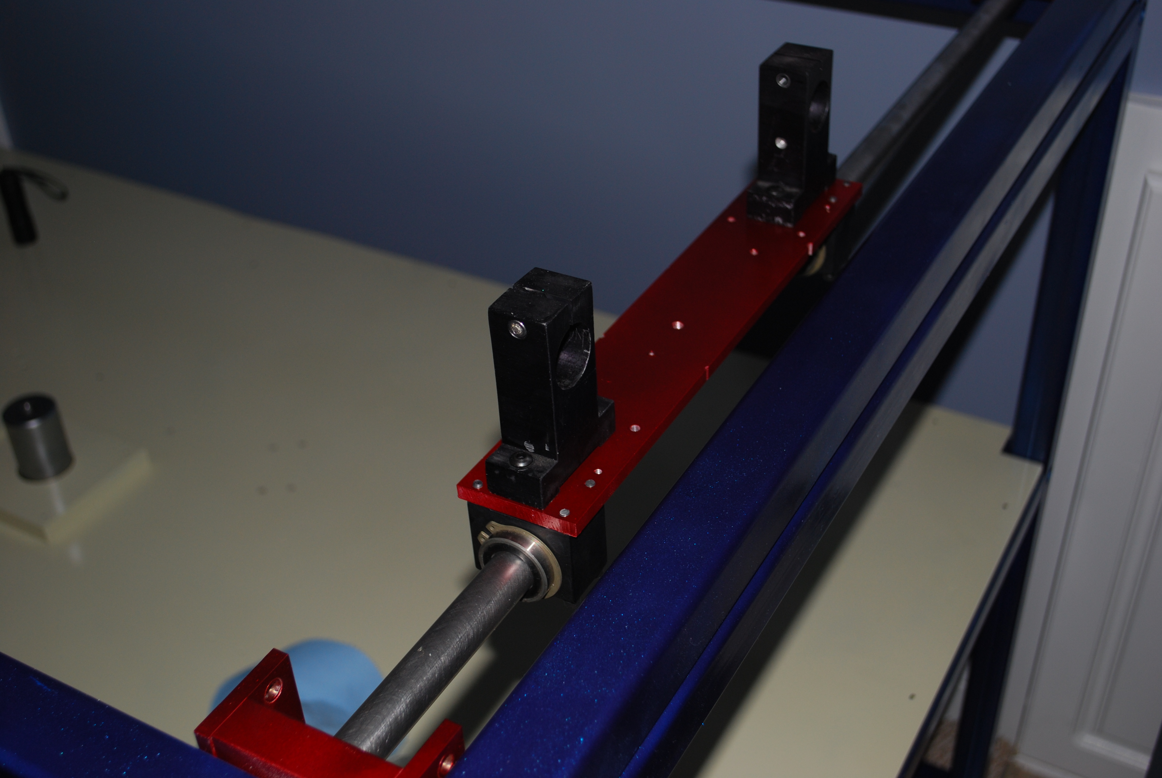
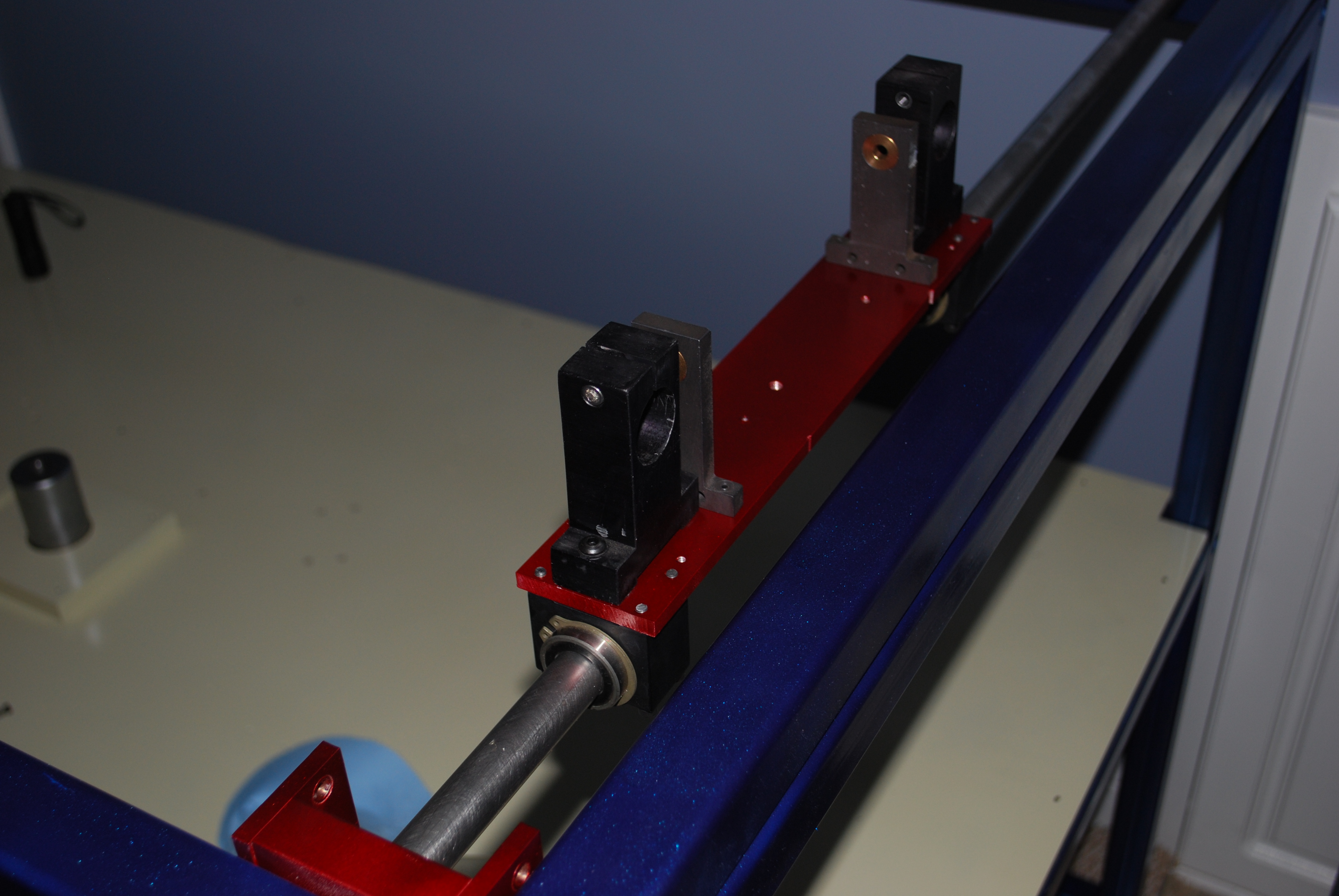
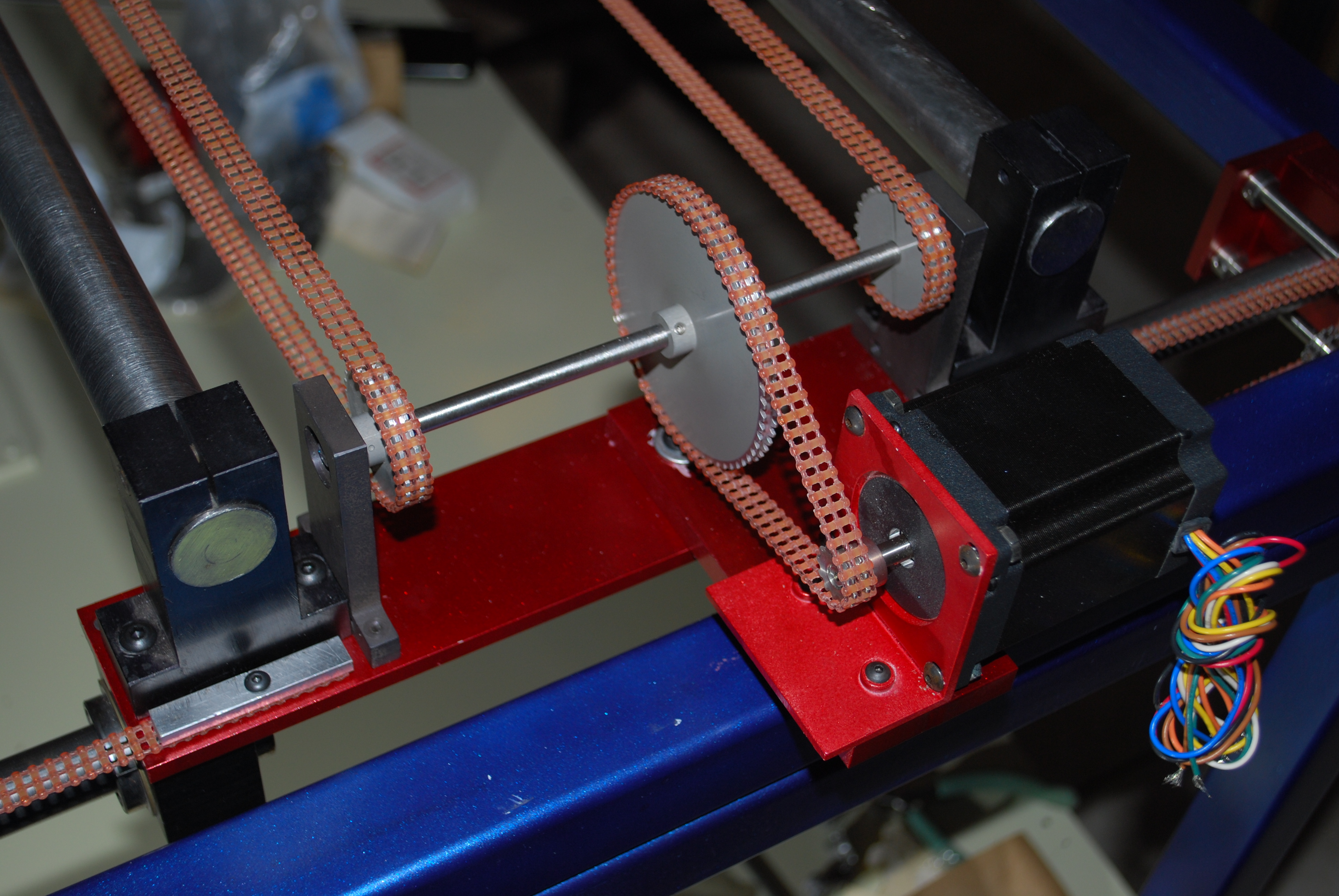
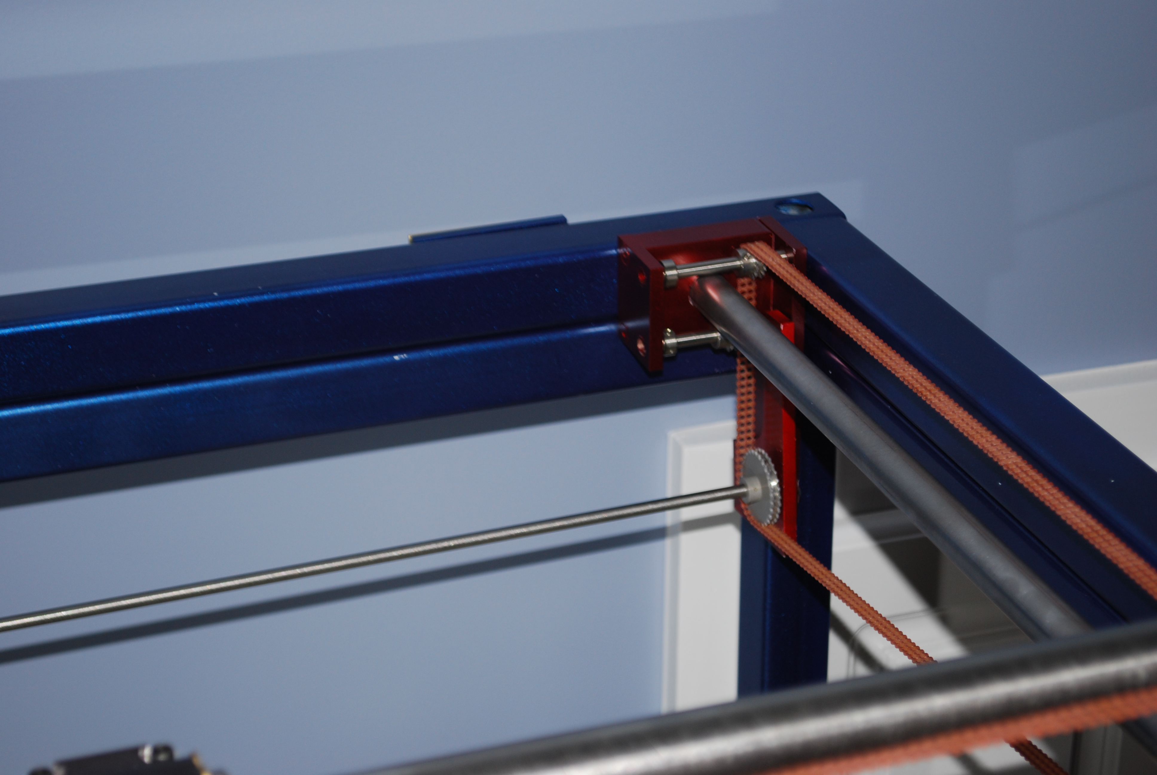
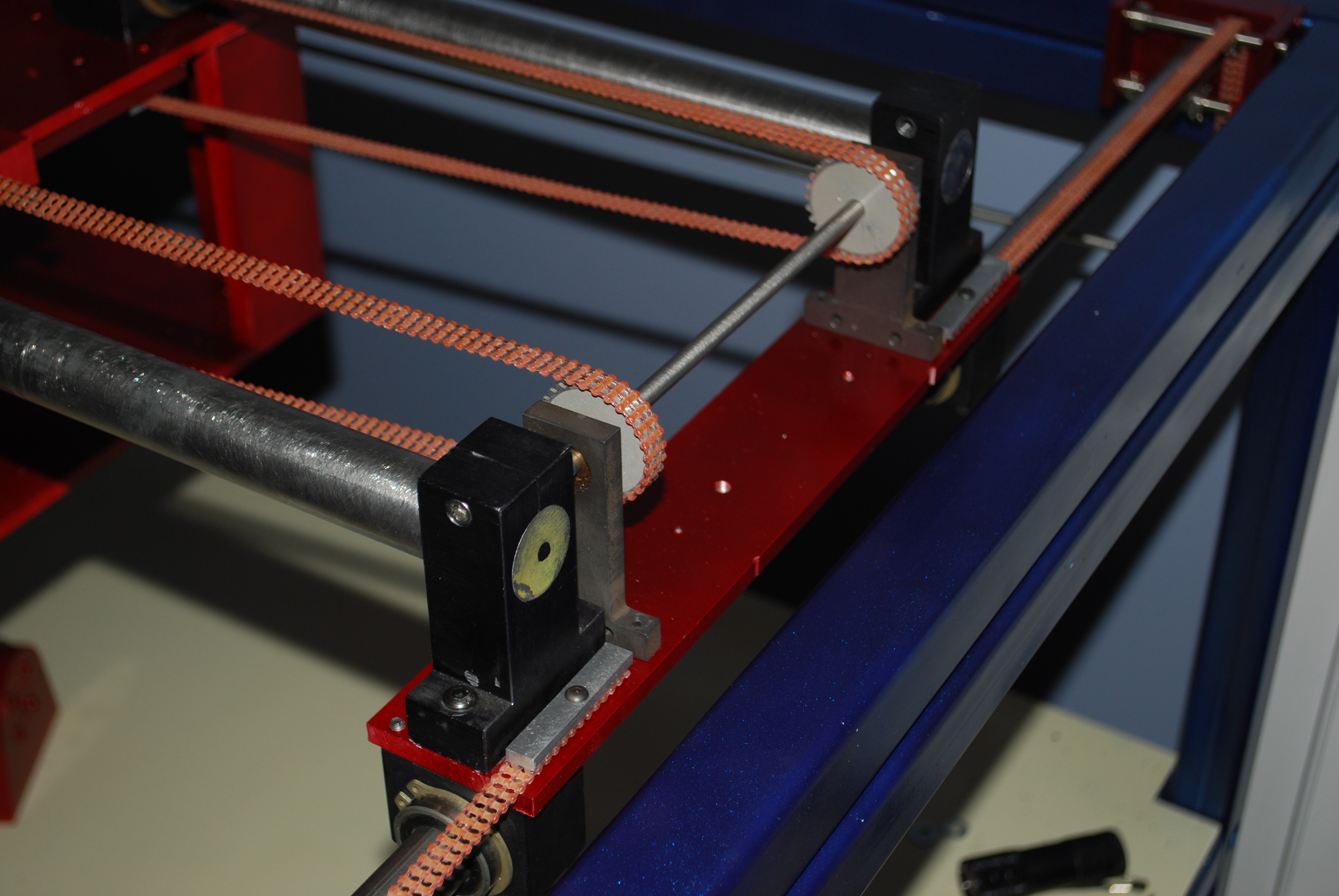
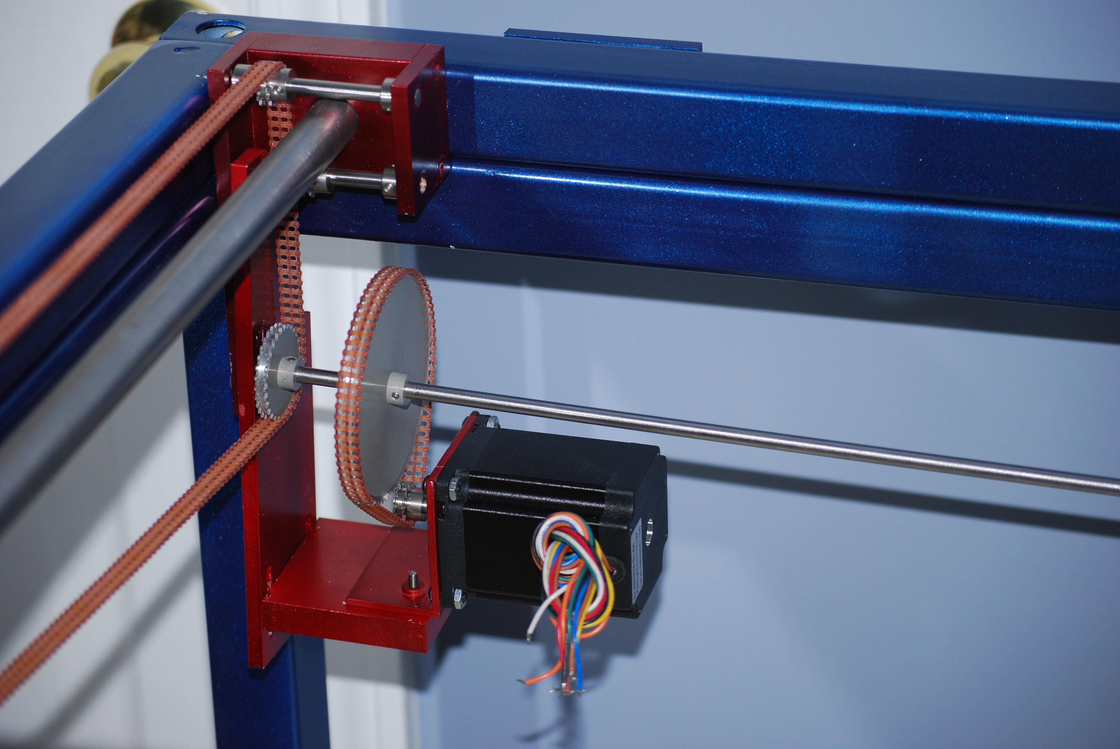
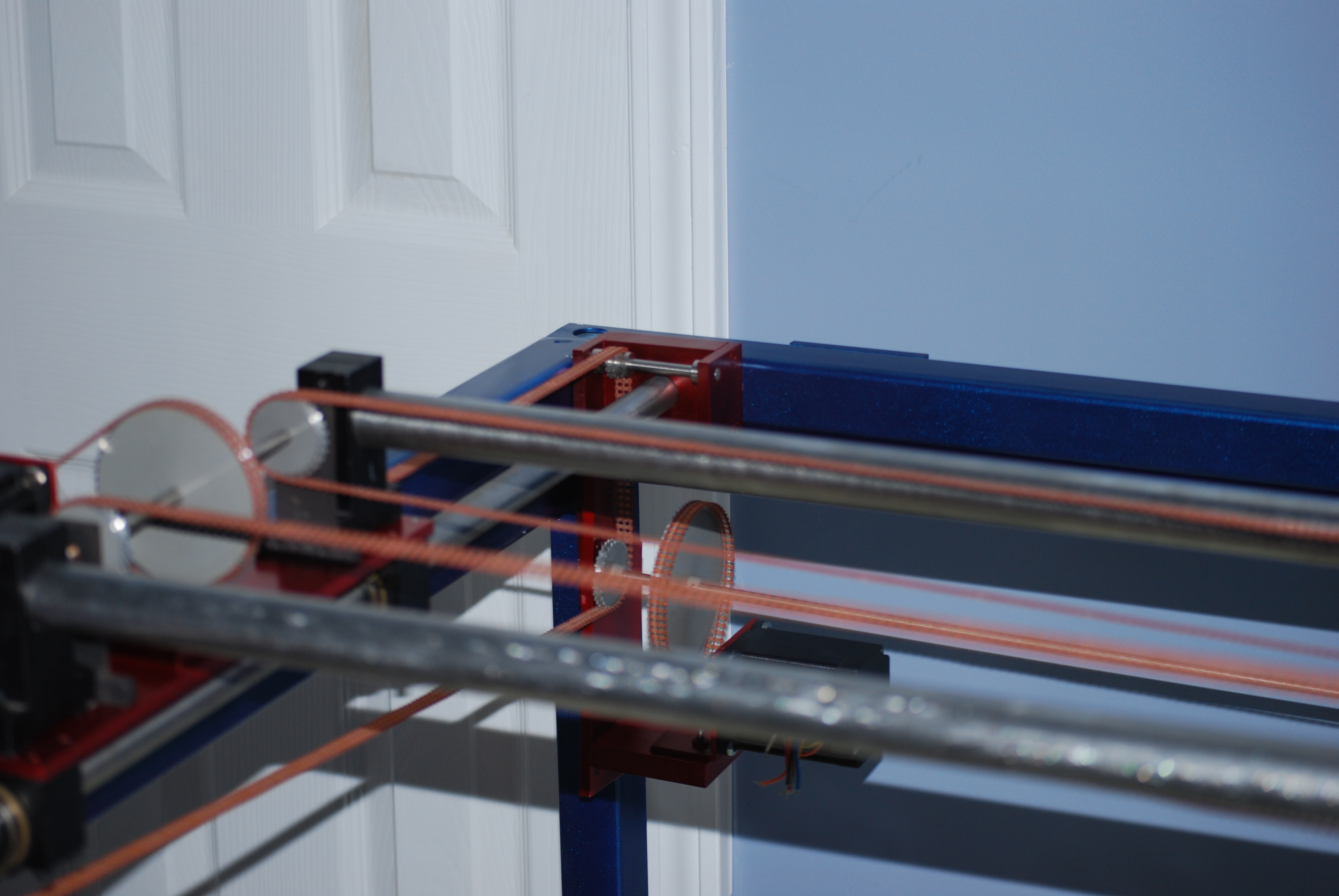
With the top frame in place, the motion hardware was installed. First the .75" Y-Axis rods and supports were attached to the top. Next the supports for the X-Axis were attached to the linear bearings on the Y-Axis.
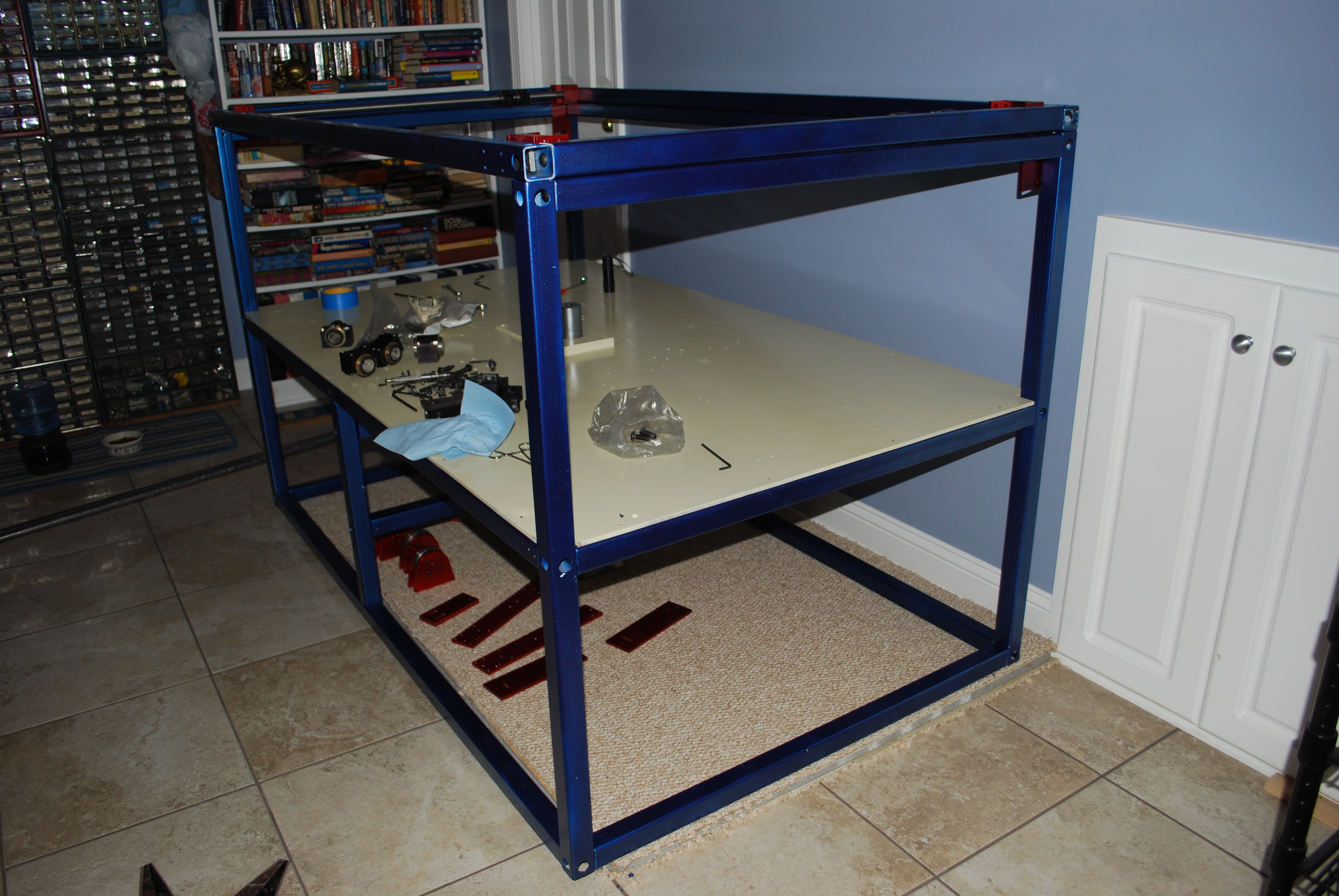
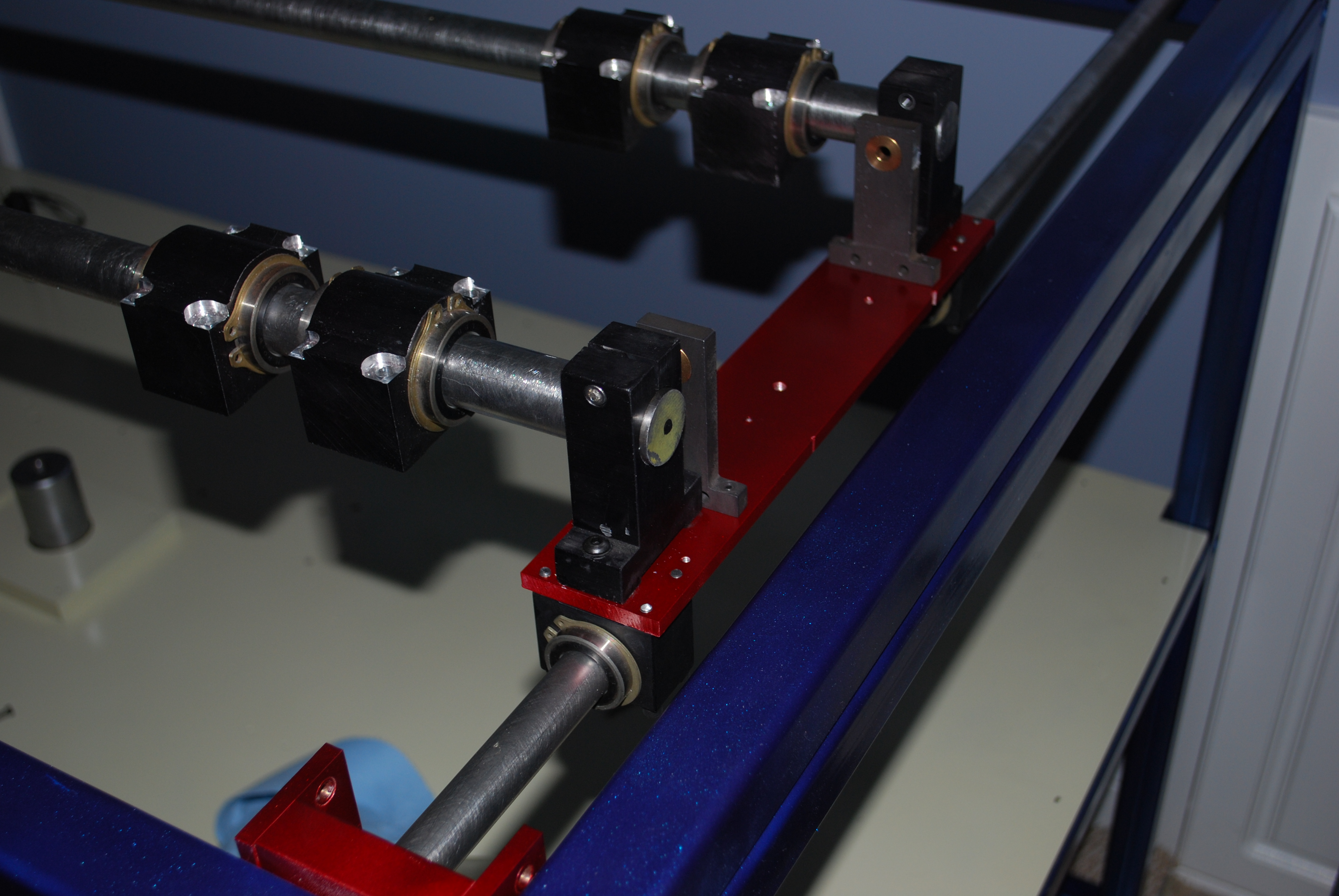
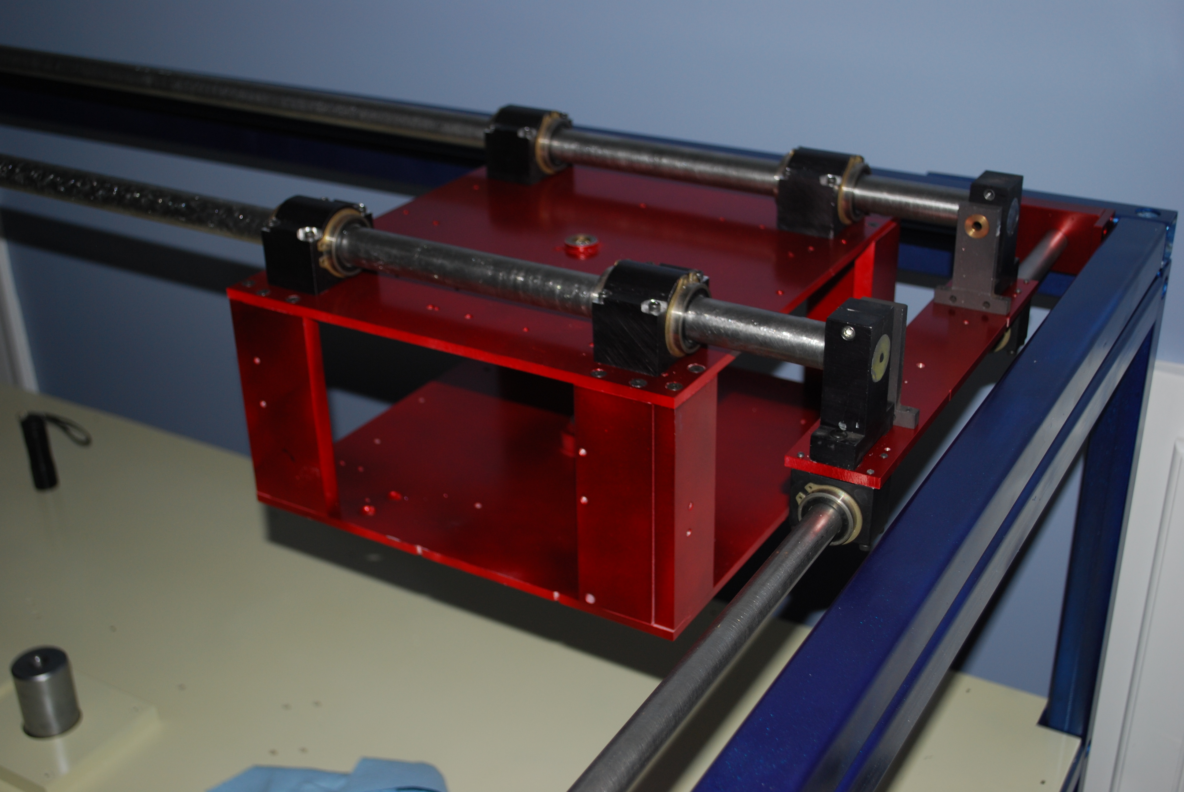
With the 1" diameter X-Axis rods in place, the carriage was added. Followed by the bearing supports for the turntable.
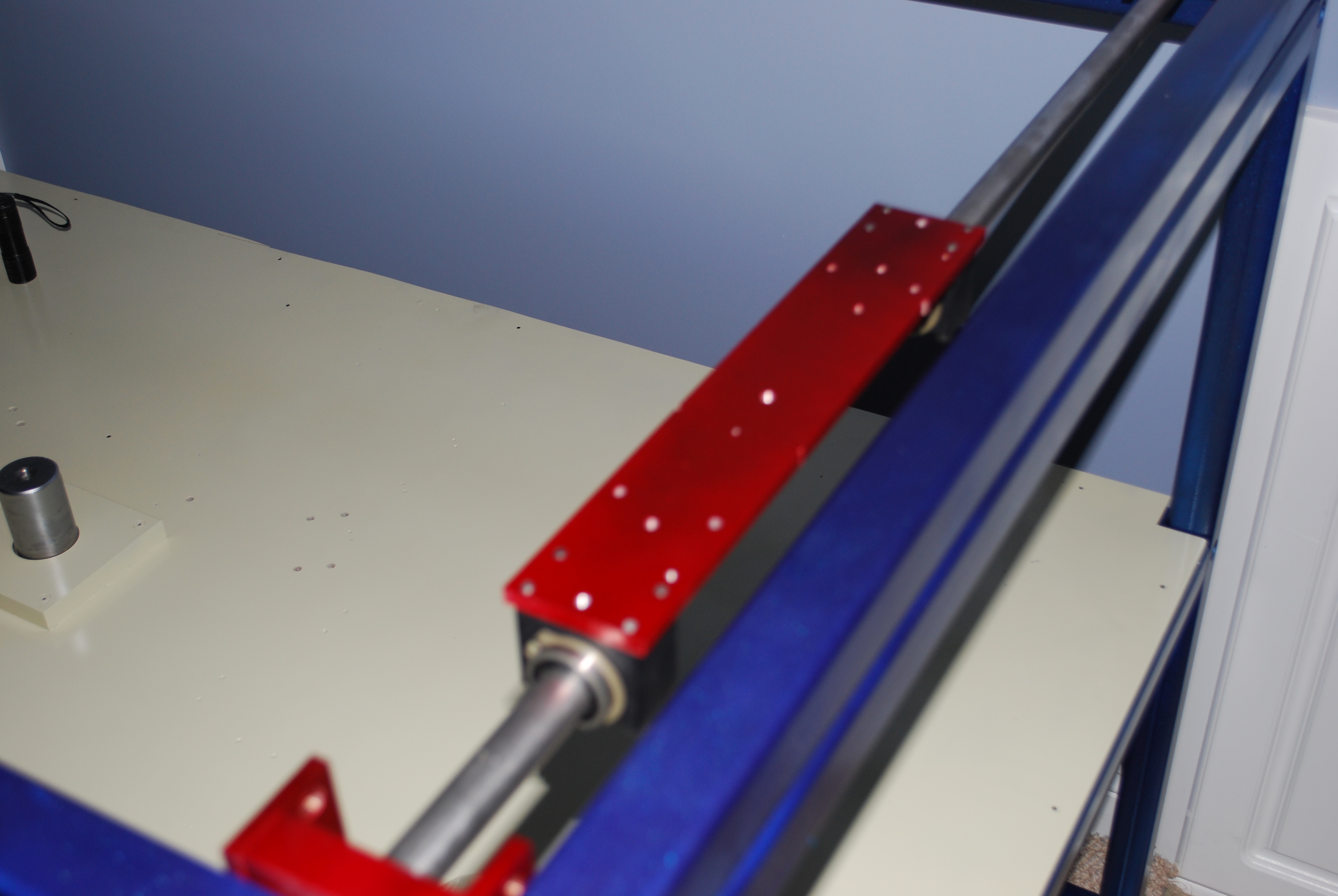
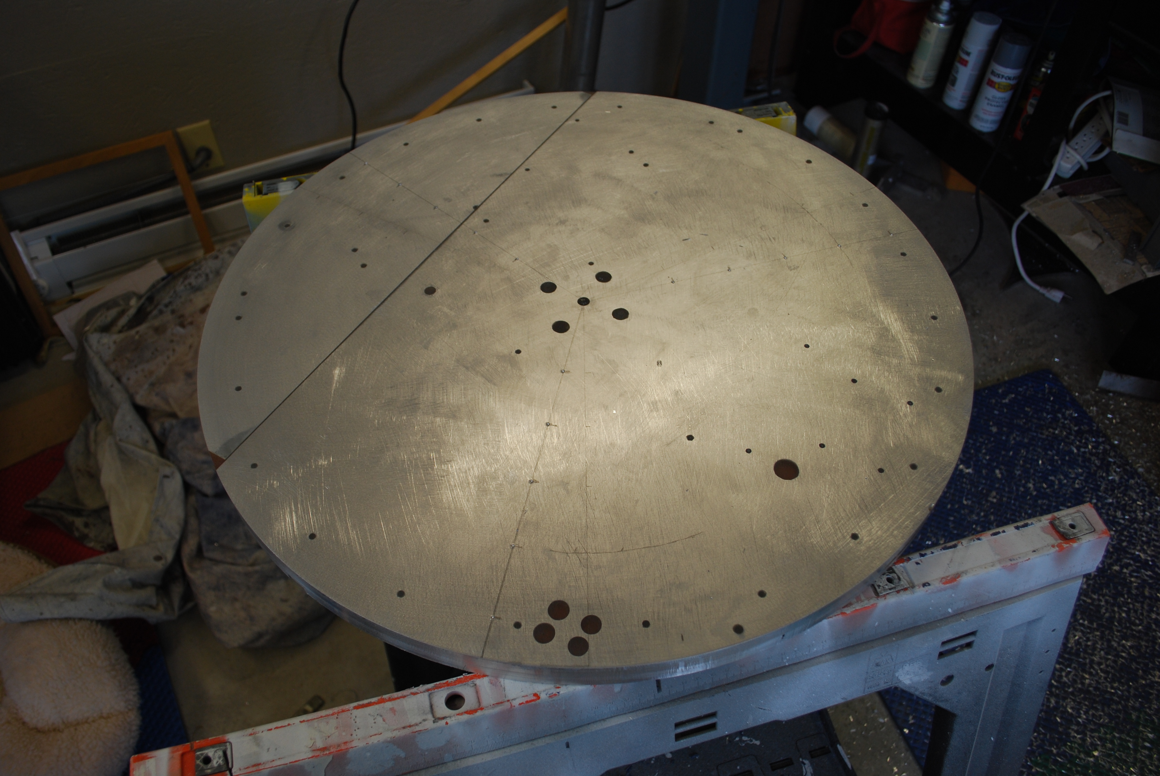
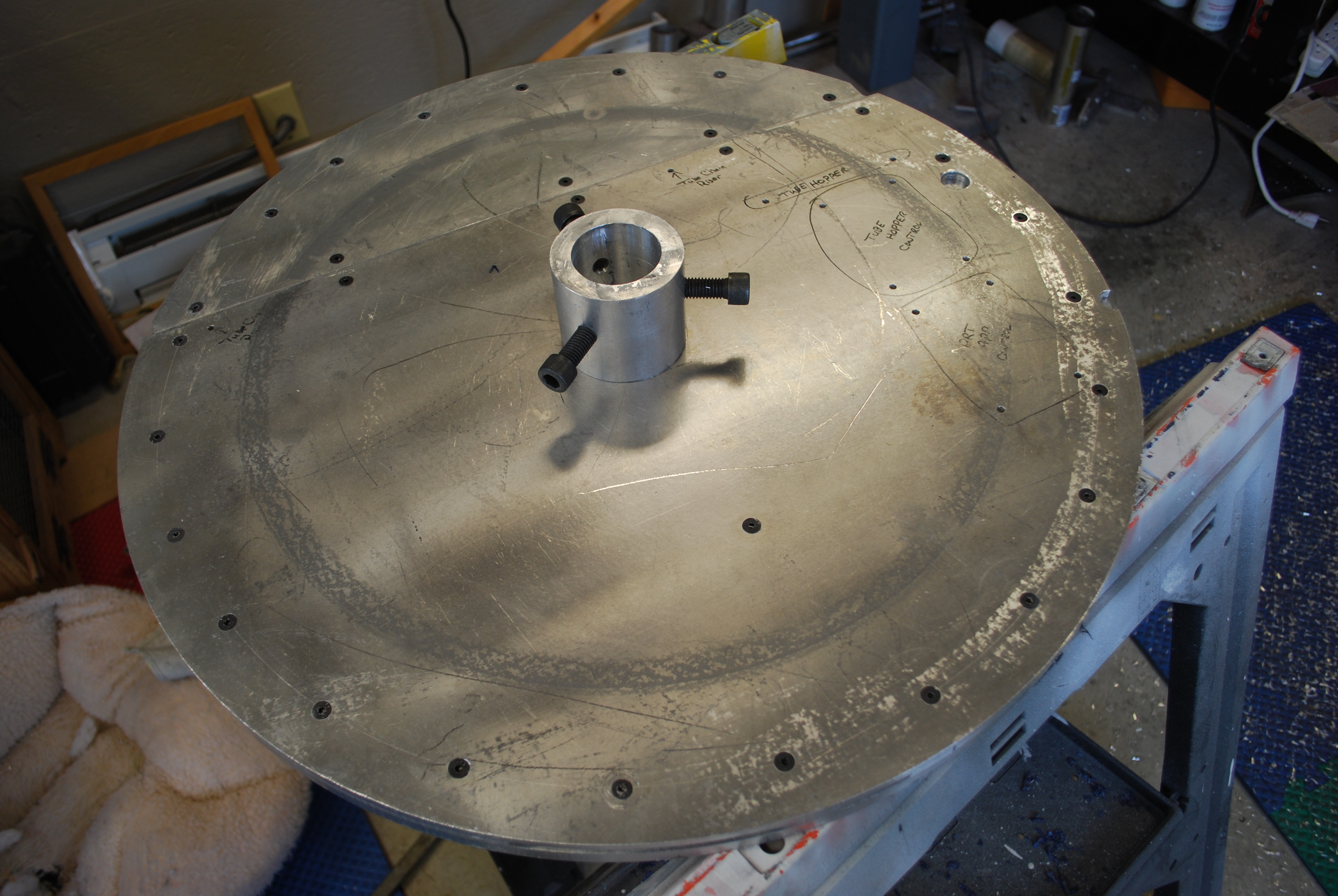
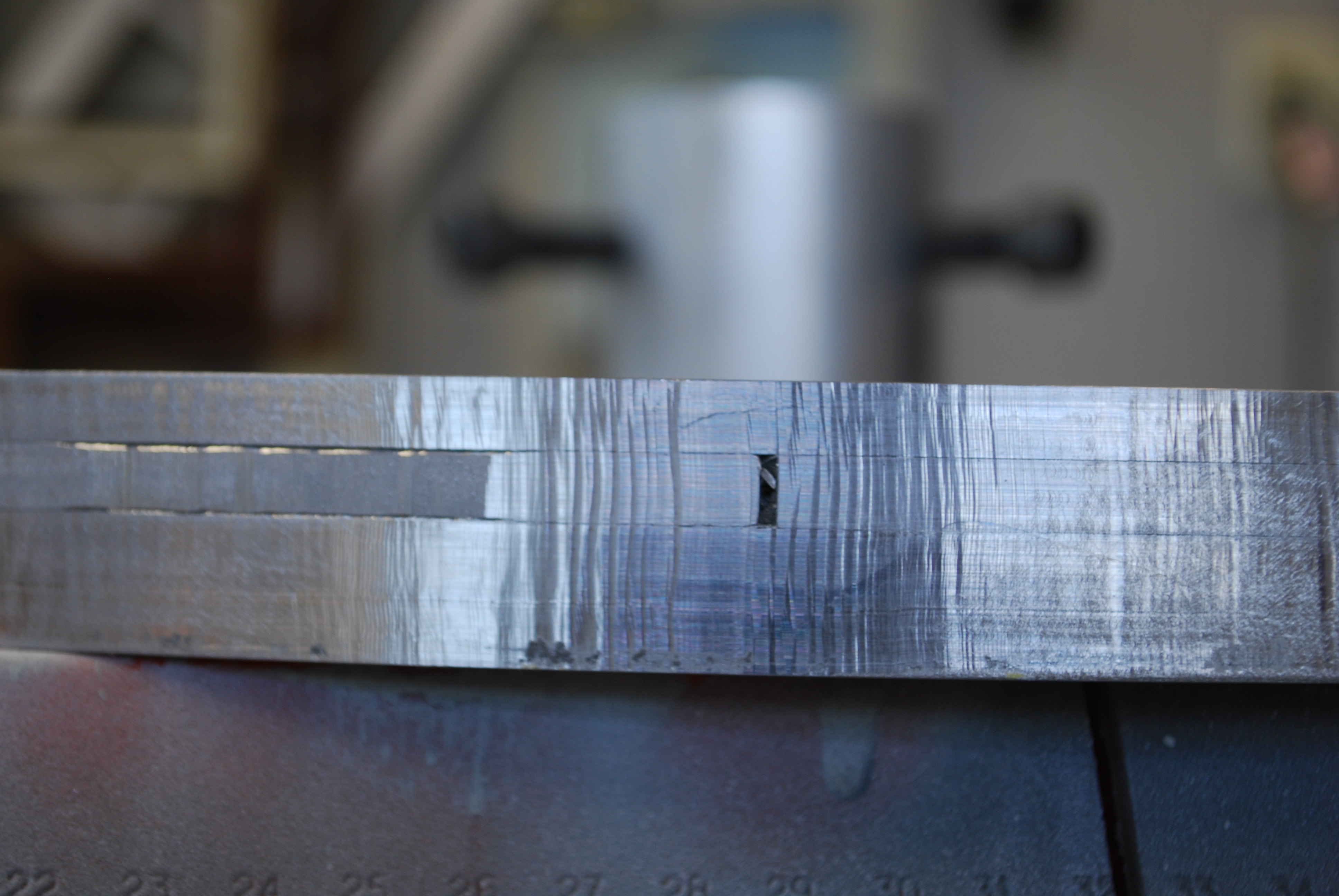
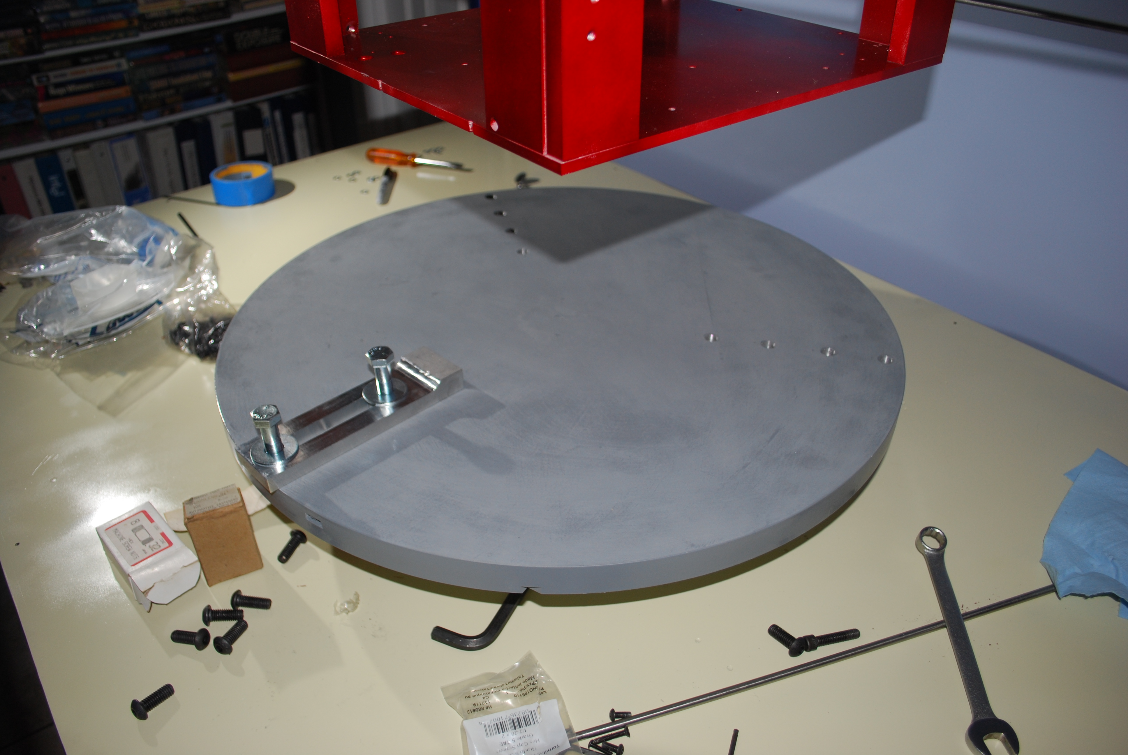
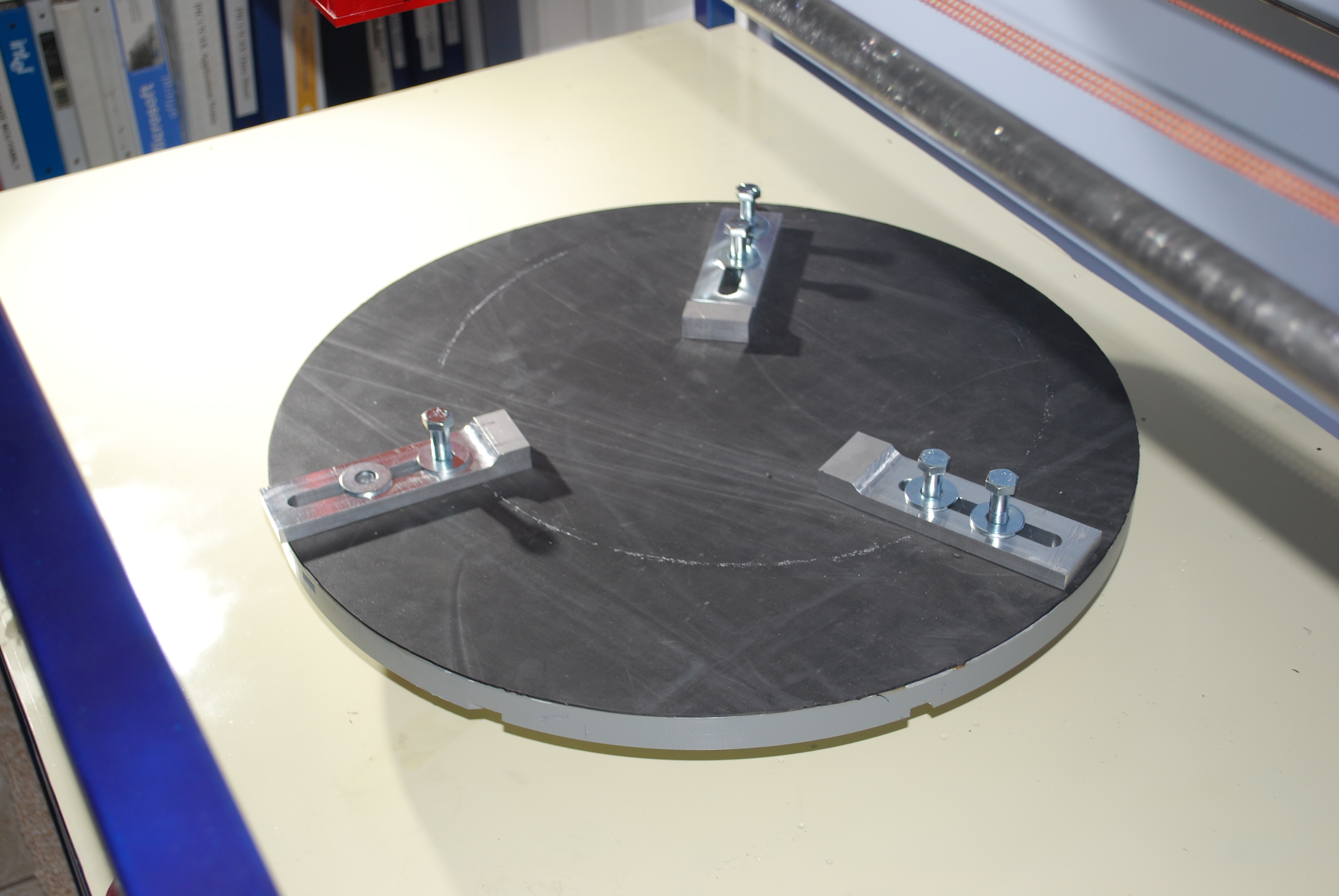
The 24" diameter turntable is actually 4 layers of .25" Aluminum which is screwed together, It was attached to one end of my milling machine table and hand turned against an end mill. This gave me a round, smooth surface. The top was covered with epoxy and sanded down to a flat surface. The bottom shot shows the 3" diameter Aluminum piece that was milled out to fit the 2" diameter shaft. This was screwed to the 1" thick plate. The turntable was painted with primer and epoxy enamel before being covered with a layer of rubber mat. There are three groups of four 1/2 x 20 holes located 120° apart which will hold the mirror clamps.
Once all the parts were in place, the dual chain (three 1/32" diameter stainless steel cable covered with polyurethane) was attached to the moving parts. Stepper motors were added.
And this is the current state of the hardware as of September 10, 2009. |
|
Please address general comments to web@dv-fansler.com This page was last modified:
01/22/14 |