Home Up Legal Union

Dec Encoder
Wedge Modifications Dec Encoder Hand Controller CCD LX200C AHC New Motors


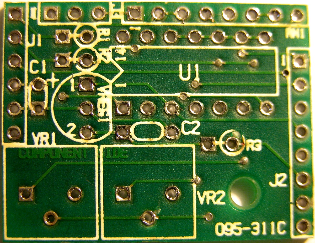
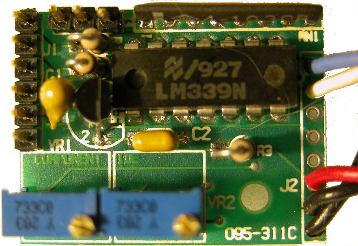
In late 2007, I went outside to do some equatorial alignment work on my LX200.  On power up the declination axis just sat there and shimmied - turning the unit off and back on, the declination axis would run at high speed until I hit the N or S button, then it would sit there and shimmy.  Bummer.  I started by searching the MAPUG archives and then links from there for declination problems.  There is a lot of info on the LX200 out there.  B. S. Jones had posted a schematic of the encoder board - which appears to be the same board for R.A as declination.  The primary difference appears to be an external addition of a Hall Effect Sensor to determine the position of the R.A worm.  

I removed the declination encoder board from my LX200 (two screws and unplug the cable in the arm - watch out for a spring the pushes the declination worm against the worm gear).  The board was bought inside where I ran it from a power supply and could observe signals with my oscilloscope.  The board provides a pair of test points for the raw signal from a couple of photodetectors in the motor assembly.  I had an imbalance as seen here.

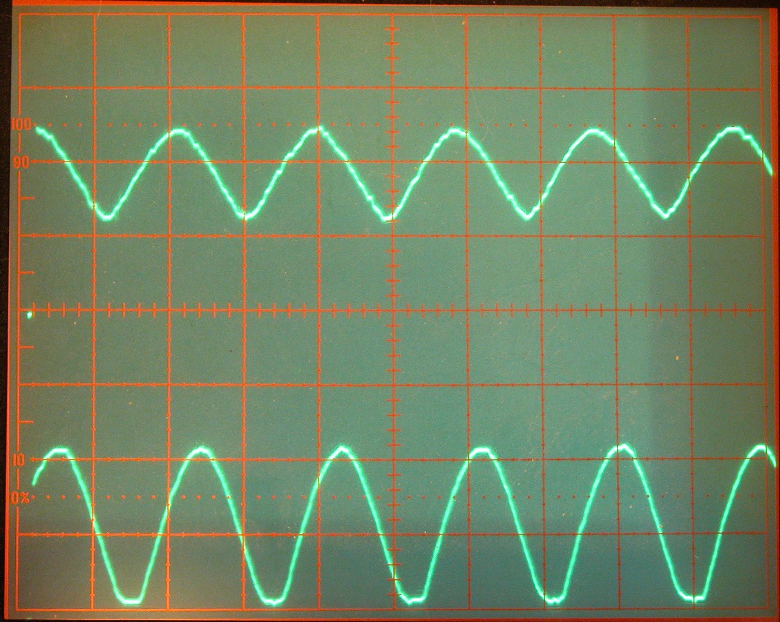
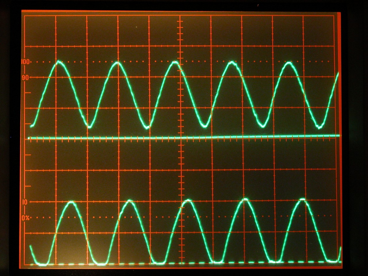
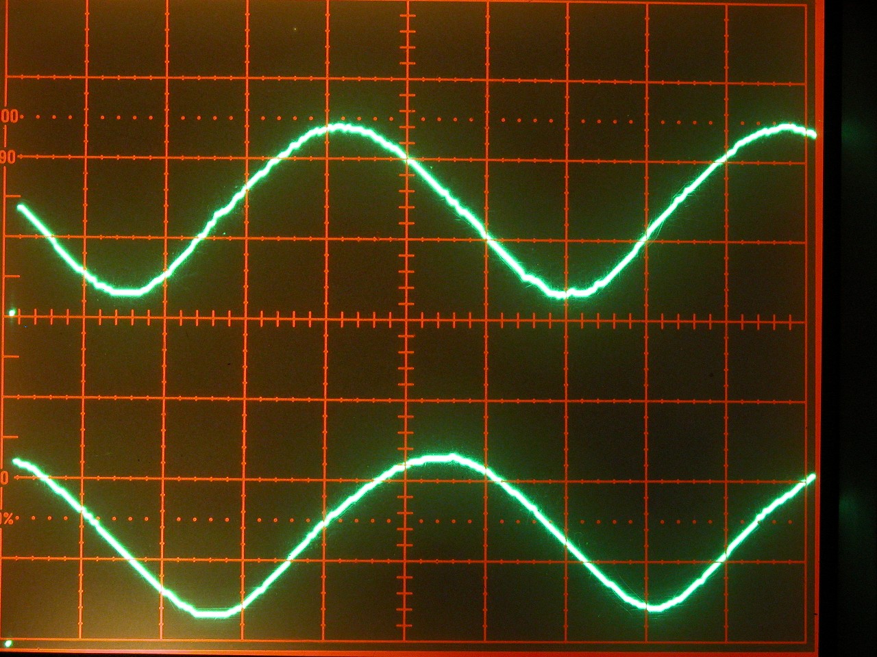
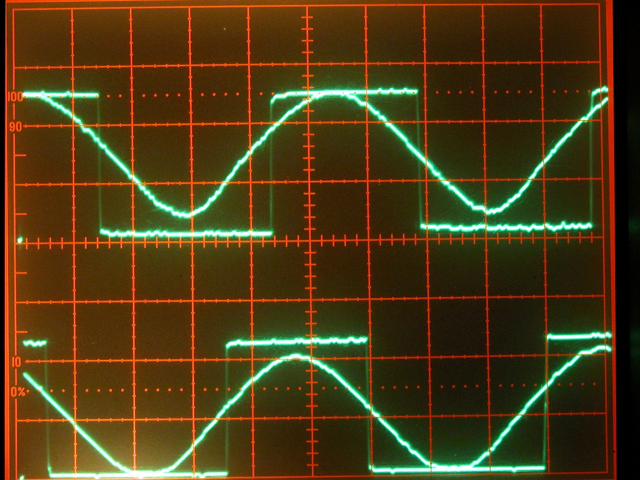
All pictures are take with each vertical division 2v, and the bottom line as 0v for the bottom trace and the center horizontal line as 0v for the upper trace.


After a small adjustment on one of the 2 trimmer pots, the signal looked better.


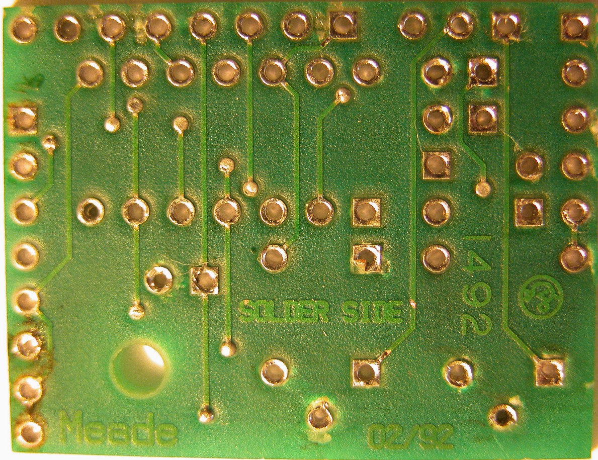
But I decided to heed a suggestion I had read and replace the 1 turn trim pots with multi-turn trim pots.  I purchased a pair of 20k Bourns 3696Y-1-203LF from Newark Electronics.

While waiting on the pots to arrive, I decided to strip the board for an examination.  Here are a couple of pictures showing   the front and back of the bare board.   With all components off the board, I made a new schematic.  As it turns out, I found one correction from B.S. Jones schematic - the resistor pack  contains 4 separate 10k resistors rather than the 7 resistors with a common bus.  An easy mistake to make with the resistor pack in place with this circuit.  The new schematic can be downloaded from here.  I also made a PCB layout of the board - just components that can also be downloaded.

Once the new trim pots arrived, I repopulated the board and adjusted the pots for the best signal.  As seen from the picture I have a good ~5v sine wave from each photodetector.


Here is an overlay picture of the two sine waves and the output from the comparator for each sine wave, giving a nice clean square wave, roughly 90° apart.


The reassembled board ready to be re-installed into my LX200


Please address general comments to web@dv-fansler.com

This page was last modified: 01/22/14
This Document is Copyright © 1998-2014 by David V. Fansler  All rights reserved.
Legal Notice